Maintenance3103−1/A1 RT-flex50-D
Wärtsilä Switzerland Ltd
2/ 3
4.1 Setting the checking equipment
With the running gear in situ, the crank to be measured has to be turned corre-
spondingly after B.D.C. The checking equipment can now be clamped next to the
connecting rod into the provided center punch marks.
⇒ Pretension the dial gauge of checking equipment 94305 and turn the latter
around its own axis for its proper settling.
⇒ Dial gauge must not deviate more than 0.01 mm. Set subsequently dial gauge
to zero.
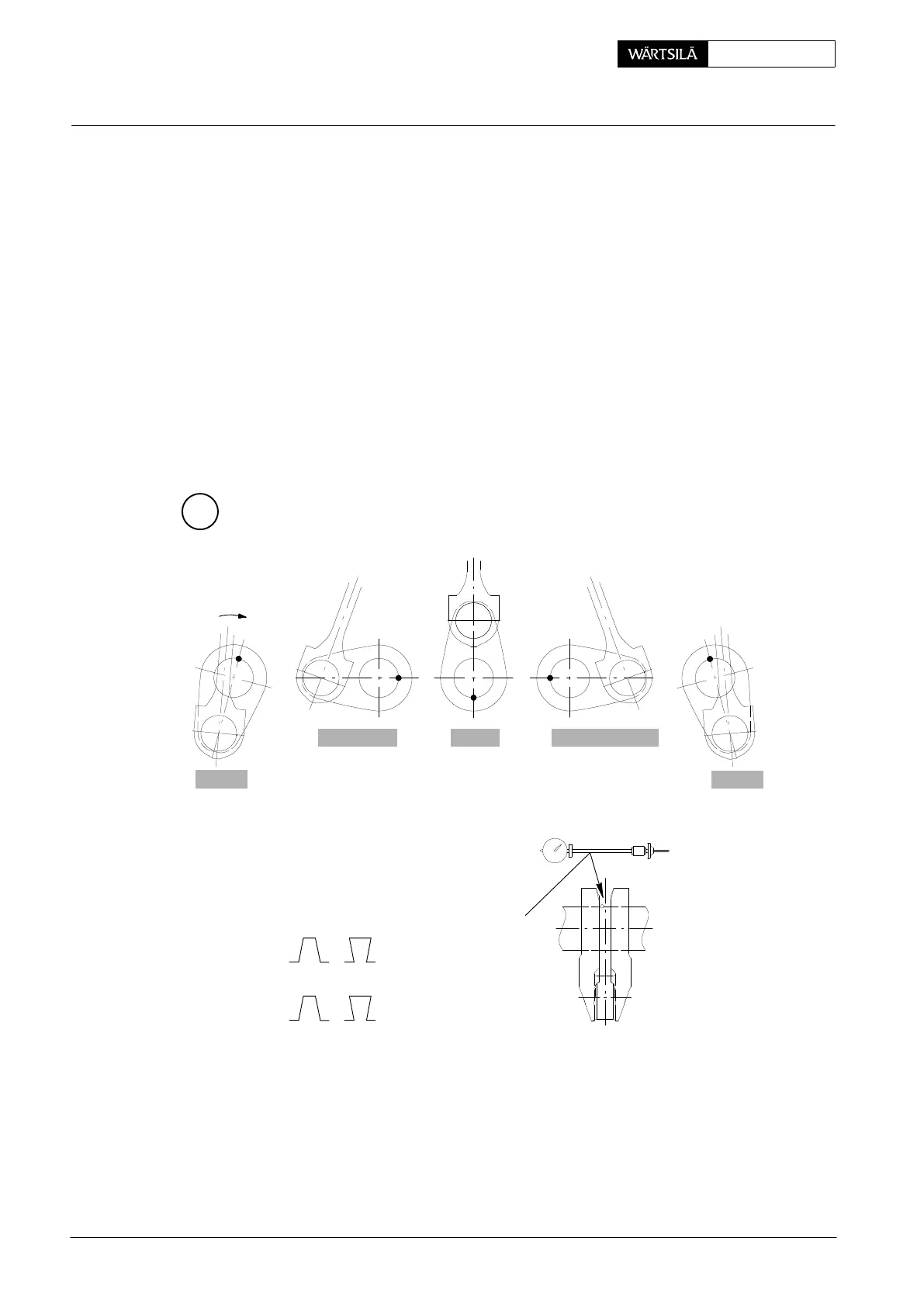
⇒ Turn crankshaft by means of turning gear, reading the dial gauge in the shown
crank positions at B.D.C. − EXHAUST SIDE − T.D.C. − FUEL SIDE − B.D.C
and noting down the values.
D The last value at B.D.C. is for checking. With correctly carried out measuring
procedure it should be again nearly zero. If it deviates more than 0.05 mm
from the first reading, then the measuring must be repeated.
B
94305
000.266/93
CRANK DEFLECTION
SIGN ON DIAL GAUGE
+ −
− +
OR
VIEW FROM
DRIVING END
B.D.C.
B.D.C.
EXHAUST SIDE
FUEL SIDE T.D.C.
CLOCKWISE
ROTATION
2011-12
Measuring Crank Deflection