Maintenance5801−1/A1 RT-flex50-D
Wärtsilä Switzerland Ltd
2/ 3
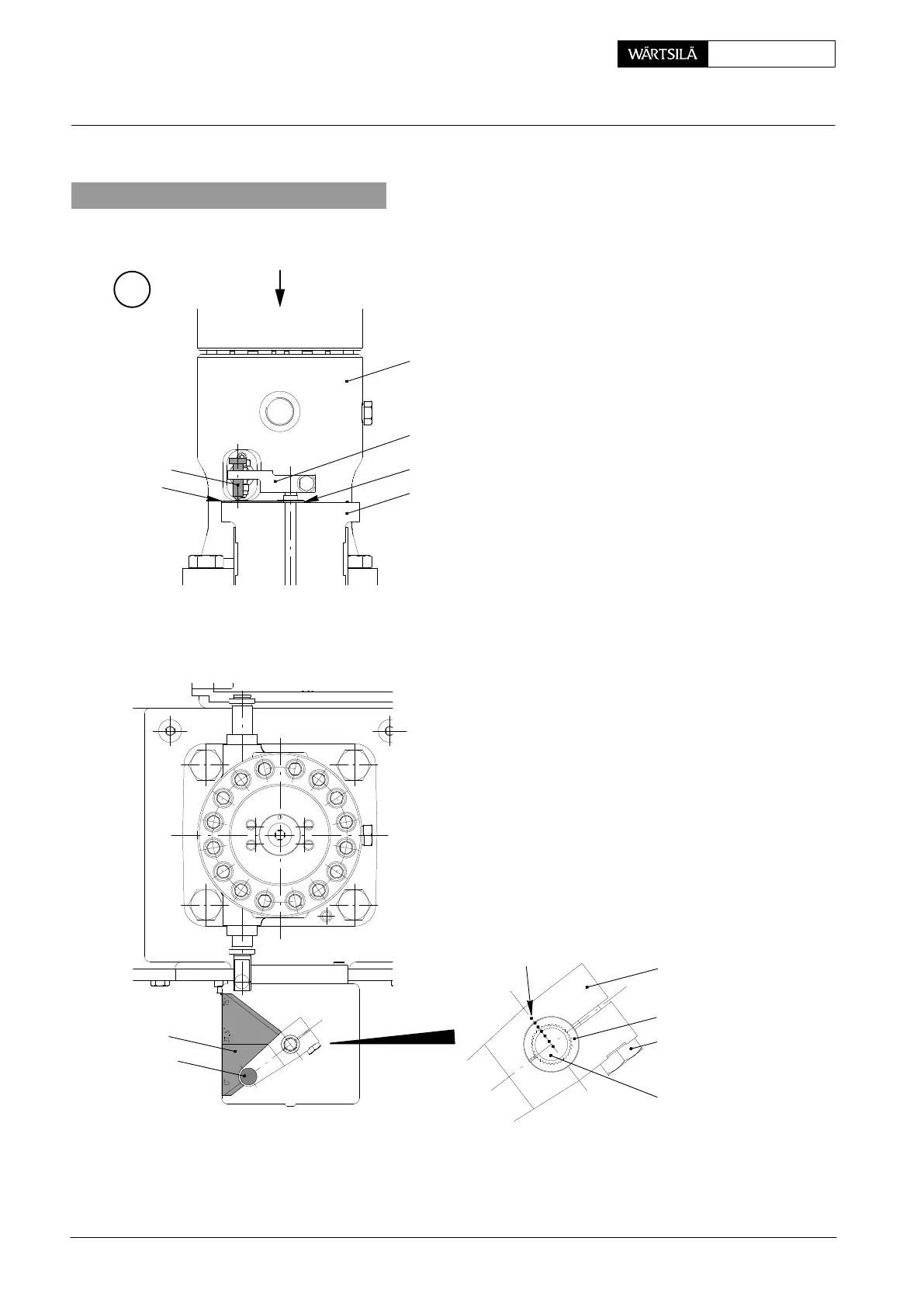
2. Adjusting of regulating linkage
⇒ Place adjusting scale 94575 on ac
tuator 2 as shown in Fig. ’B’. Pus
the tool against centring flange
aligning it parallel with the outer ac
tuator edge simultaneously. Main
tain this position during the followin
adjusting works.
⇒ Rotate actuator shaft 4 in counter
clockwise direction until the interna
stop of the actuator (minimum stop
⇒ Put lever 5 with inserted sleeve 6 an
adjusting pin 94575a on actuato
shaft 4 so that the pinpoint points a
0_-line as exactly as possible.
⇒ Slightly tighten screw 7.
⇒ Rotate lever 5 to 75_-mark (max
mum stop) so that also in this pos
tion the pinpoint points at 75_-line a
exactly as possible.
⇒ Compensate possible difference
with regard to 0_- and 75_-lines b
means of turning lever 5 on sleeve 6
⇒ Tighten screw 7.
⇒ Mark the lever position to the actua
tor shaft with the aid of slight cente
punch strokes ’MA’.
⇒ Remove the adjusting tools.
B
012.883/05
1
5
2
3
I
I
5
6
7
4
MA
94575a
94575
94575a
94575
egulating Linkage: Adjusting with Heinzmann StG 10-01 Actuato
2010