Maintenance
5564−1/A1
RT-flex50-D
Wärtsilä Switzerland Ltd
1/ 3
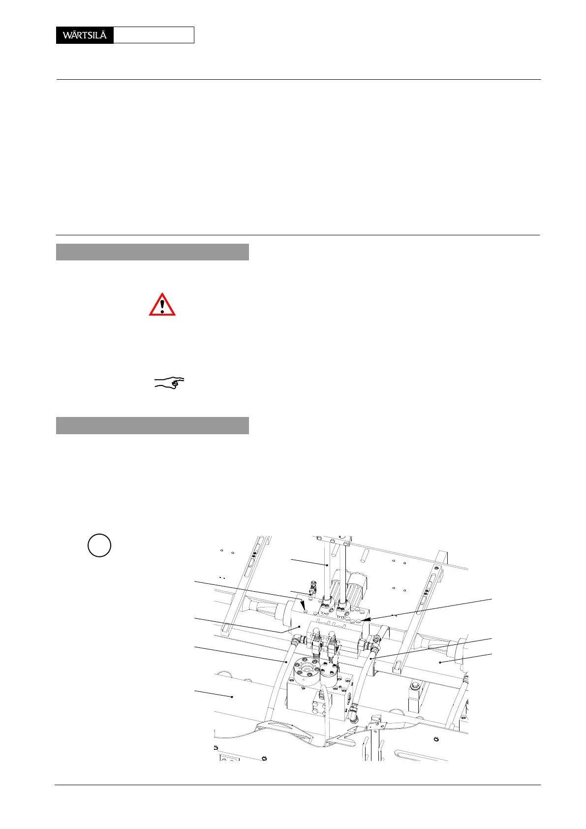
Tools: Key to Illustrations:
1 Lifting plate 94584 1 Servo oil inlet 10 Screw
1 Withdrawing tool 94589 2 Servo oil outlet 11 Lip seal
3 Leakage fuel return 12 Position sensor
4 Fuel rail 13 Dowel pin
5 Servo oil rail 14 Connecting nipple
6 Fuel pressure pipe 15 Filter holder
7 Injection control unit 16 Oil filter
8, 8a Screw 17 Circlip
9 Pre-control valve 18 O-ring
1. General
When working on an injection control unit in principle the engine has to be stopped.
Attention! Follow the detailed instructions in 0510−1 of the Operating Manual
without fail!
Maintenance works on the injection control unit may be carried out only by the
manufacturer as a matter of principle. However, if troubles have been detected on
the injection control unit during operation, it must be replaced by a revised unit,
following the instruction below.
Remark: No maintenance work is provided for pre-control valves (rail valves) 9. If
necessary they must be replaced as a whole unit!
2. Removal
⇒ Remove fuel pressure pipings 6 from injection control unit 7 according to
8733−1.
⇒ Remove screws 8 and 8a.
A
016.613/08
8a
6
3
8
7
2
5
1
4
njection Control Unit
emoval and Fitting
2010