Maintenance
8752−1/A1
RT-flex50-D
Wärtsilä Switzerland Ltd
1/ 5
Tools: Key to Illustrations:
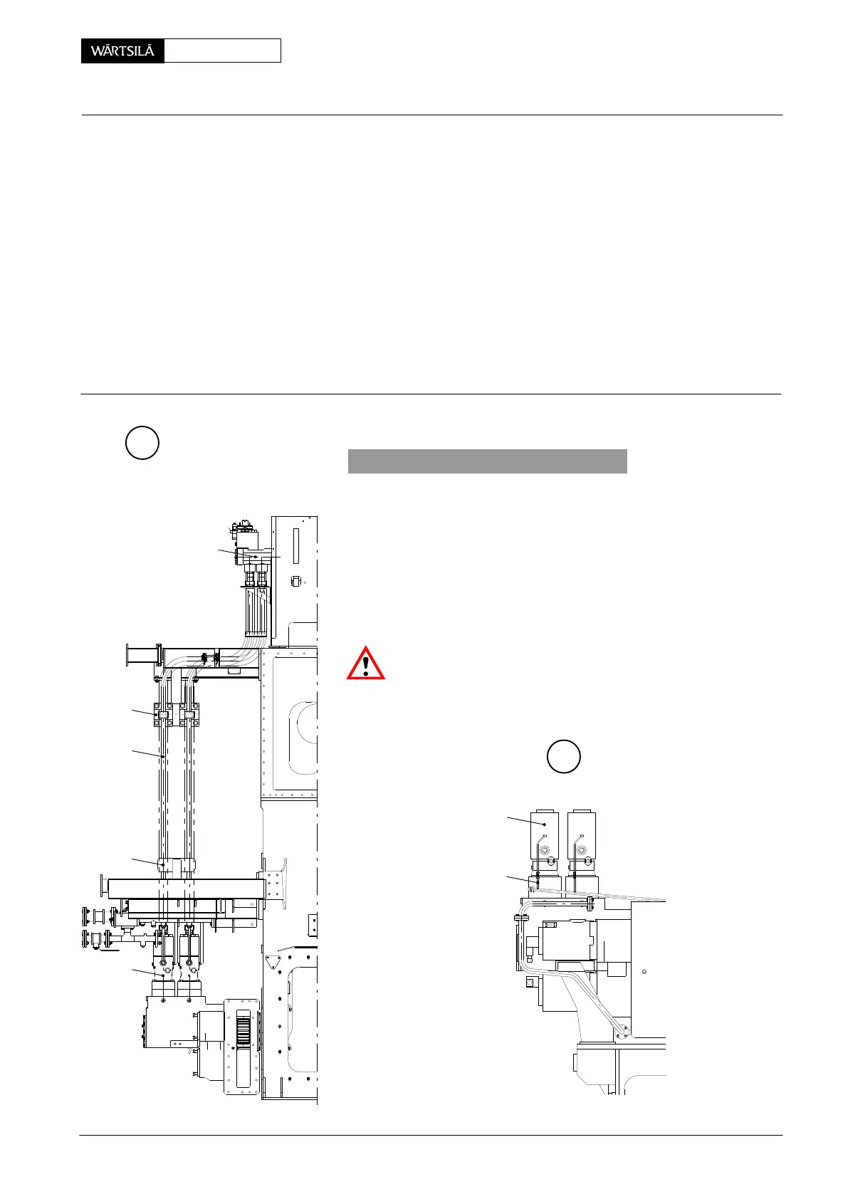
1 Regrinding device 94870 1 Fuel pressure piping 13 Pressure spring
consisting of: 2 Fuel pump 14 Non-return valve
1 Screw-on sleeve 94870e 3 Fuel rail 15 Claw
1 Grinding tool 94870f 4 Screw 16 Thrust ring
1 Lock nut 94870g 5 Mounting clamp 17, 17a Holder
1 Template 94870h 6 Screw 18 Leakage fuel pipe
7 Screw 19, 20 O-ring
1 Torque wrench 8, 8a Flange
9 Fuel pump cover DF Sealing face
10 Intermediate ring EC Emery cloth
11 Valve housing HD Hand drill
12 Lip seal LB Leakage fuel bore
A
019.070/09
2
1. General
The engine must be stopped, the fuel supply pump switched o
and then the fuel pressure pipings can be drained via bores ’L
(section III-III) and leakage fuel pipes 18.
D For that screws 7 must be loosened, flange 8a and inte
mediate ring 10 (section I-I), as well as screws 6 an
flange 8 at fuel pump cover 9 pushed back in order to se
arate fuel pressure piping from its sealing faces.
Non-return valves 14 prevents the fuel rail from discharging
Risk of accident! Make sure that the steam supply is close
before loosening the screwed connections to the heating pipe
1
3
B
016.520/08
18
2
17a
17
uel Pressure Piping
emoving, Fitting and Regrinding 5 and 6 Cylinder Engine
5 & 6 Cyl. / 2010