Maintenance2751−1/A1 RT-flex50-D
Wärtsilä Switzerland Ltd
4/ 7
2. Fitting
⇒ Clean all the joint faces on the exhaust valve and in the cylinder cover and
check them for damages.
⇒ Clean the soft iron ring of 2 mm thickness, replace it if necessary, then put it in
the cylinder cover.
⇒ Fit new O-rings in the valve cage and valve seat and oil them slightly.
⇒ Fit the complete exhaust valve suspended on RUD-eye bolt ’RC’, taking care
not to damage the threads of the waisted studs (Fig. ’E’).
D The correct position of the exhaust valve cage is determined by the cylindrical
pin set in the cylinder cover.
⇒ Smear thread of waisted stud lightly with oil.
⇒ Fit nuts 2 and tighten them firmly with round bar ’RS’.
Check seating of nuts 2 with a feeler gauge.
⇒ Mark position of nuts on a corner and their position on valve cage 7 with a felt-
tip pen (for later checks).
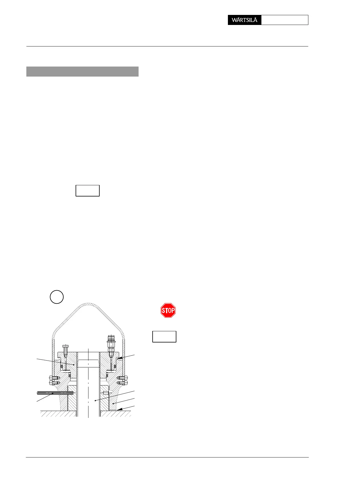
2.1 Tensioning of waisted studs
⇒ Screw pre-tensioning jacks 94252 onto waisted studs 1 as mentioned in para-
graph 1.1, however, do not turn back them.
⇒ Connect pre-tensioning jacks to hydraulic unit 94942 and actuate the latter.
⇒ Close vent screws 3 on the pre-tensioning jacks as soon as oil flows bubble-
free.
⇒ Slowly raise the pressure to 1500 bar.
Pistons 4 of the pre-tensioning jacks must never e
ceed the red limiting grooves ’BN’ (Fig. ’G’).
⇒ Tighten nuts 2 with round bar ’RS’.
Check seating of nuts 2 with a feeler gauge throug
slot ’KO’.
After tightening the nuts ascertain that these hav
been turned by about the same angle of 155_.
⇒ Release pressure to ’0’ and remove both pr
tensioning jacks.
CHECK
G
BN
1
KO
2
4
RS
2010
Removal and Fitting of Exhaust Valve, Replacing of Waisted Studs
CHECK