Maintenance5556−1/A1 RT-flex50-D
Wärtsilä Switzerland Ltd
6/ 9
4. Assembling of a fuel pump
4.1 Preparation
⇒ Clean all parts and check their condition.
Damaged parts must be replaced.
⇒ Check the lubricating oil bores in the housings and in pump cylinder 33 for free
passage using compressed air.
⇒ Replace all O-rings and rod seal rings.
K
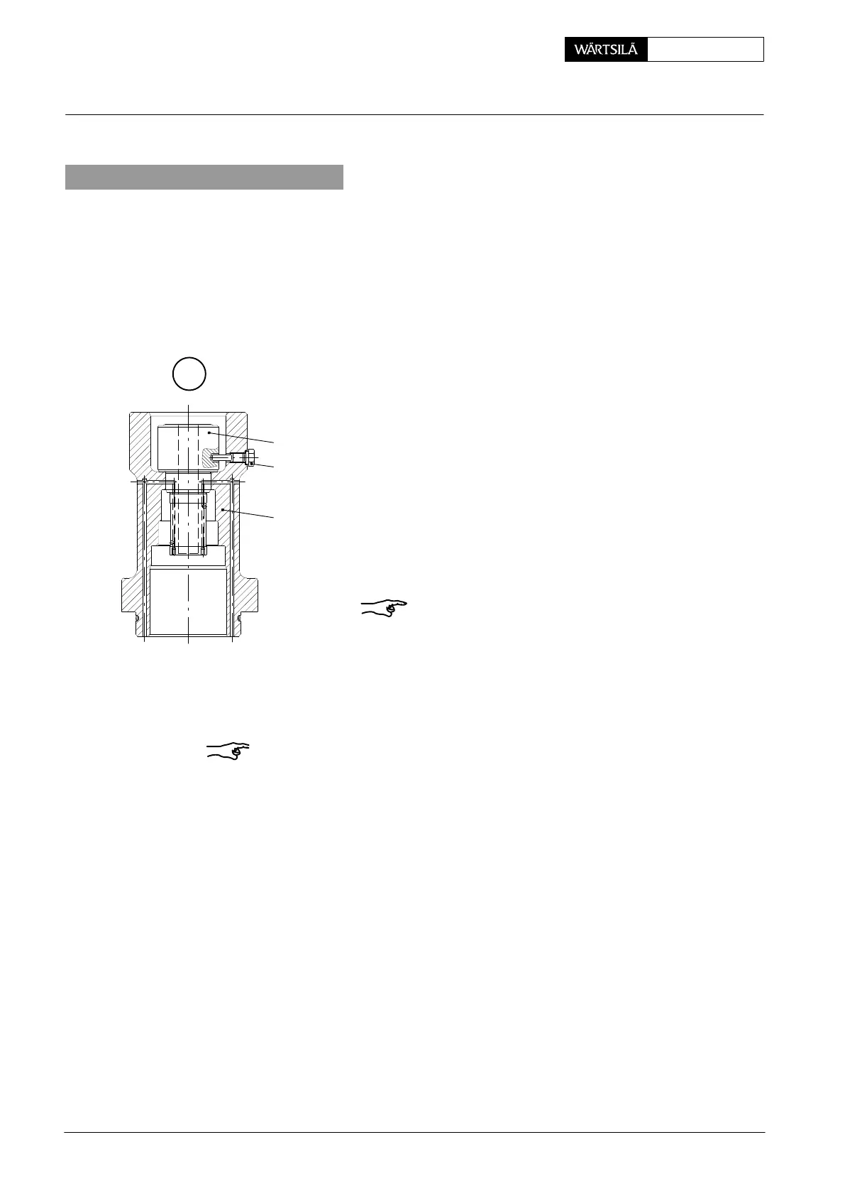
4.2 Fitting the pump cylinder
⇒ Fasten upper housing 5 in vertical position onto
work bench.
⇒ Carefully fit pump cylinder 33, aligning the groove
the pump cylinder precisely with the bore provide
for holding screw 32 in the upper housing.
⇒ Screw in and tighten the holding screw together wi
the Cu-ring.
Remark: There must be a clearance between holdin
screw 32 and the groove base!
33
32
5
008.654/00
4.3 Fitting the pump cover
Remark: Thoroughly check the joint faces for cleanness when fitting the valve
block and the pump cover (Fig. ’I’).
⇒ Fit valve block 29 with the mounted and lubricated O-rings 39 in upper hous-
ing 5. Then fit valve body 30 and compression spring 31 in the valve block.
⇒ Fit intermediate disc 34 with circlip 35 in the pump cover.
⇒ Fit pump cover 4.
⇒ Apply Never-Seez NSBT-8 to threads and head seating surfaces of screws
28, and tighten them crosswise in equal steps with a total value of 115 Nm.
2010
uel Pump: Dismantling and Assembling