Maintenance
3103−1/A1
RT-flex50-D
Wärtsilä Switzerland Ltd
1/ 3
Tool: Key to Illustrations:
1 Crankshaft checking equipment 94305 1 Flywheel
(dial gauge) 2 Pinion
1. General
The crank deflections (crankshaft alignment) must be measured in order to ascer-
tain whether the crankshaft axis has changed.
For that, checking equipment 94305 is clamped between the crank webs into the
provided center punch marks. When turning the crankshaft, the change in dis-
tance between the crank webs can be read from the dial gauge as it indicates any
opening or closing up. The smaller the variation the better the alignment of the
crankshaft. Thereby, however, the function of the checking equipment, i.e. the sign
on dial gauge “+” (standard) or “−” must be taken into consideration.
2. Checking crank deflection
D Under normal circumstances, once a year.
D In case the ship has touched ground.
D After replacing main bearing shells and again after approx. 100 service hours.
D By signs of damage to the main bearings.
3. Conditions for measuring
D Indicator valves must be open.
D The ship must be floating freely and lying in the water as horizontal as pos-
sible.
D The crankshaft must rest perfectly on all the main bearings.
A
3.1 Influences on measuring
D Engine cold or at service temperature.
D Loaded condition of the ship.
D Differing air and water temperatures.
D Strong sunshine.
D Temporary deformation of the hull and/or the engine.
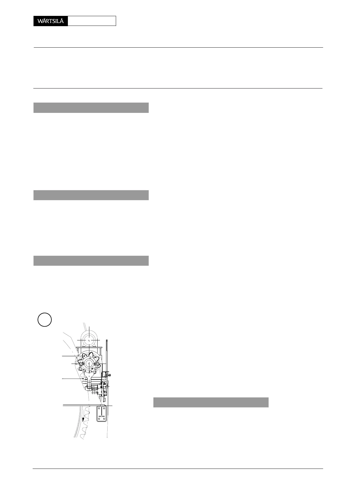
4. Measuring procedure
Despite the ordinary rotation direction of the engine, th
crankshaft must always be turned in such a manner th
flywheel 1 and pinion 2 of the turning gear are rotating a
indicated by the arrows.
TURNING GEAR ON
EXHAUST SIDE
2
1
013.051/05
rankshaft
easuring Crank Deflection
2011-12