Maintenance
2708−2/A1
RT-flex50-D
Wärtsilä Switzerland Ltd
1/ 3
Tools: Key to Illustrations:
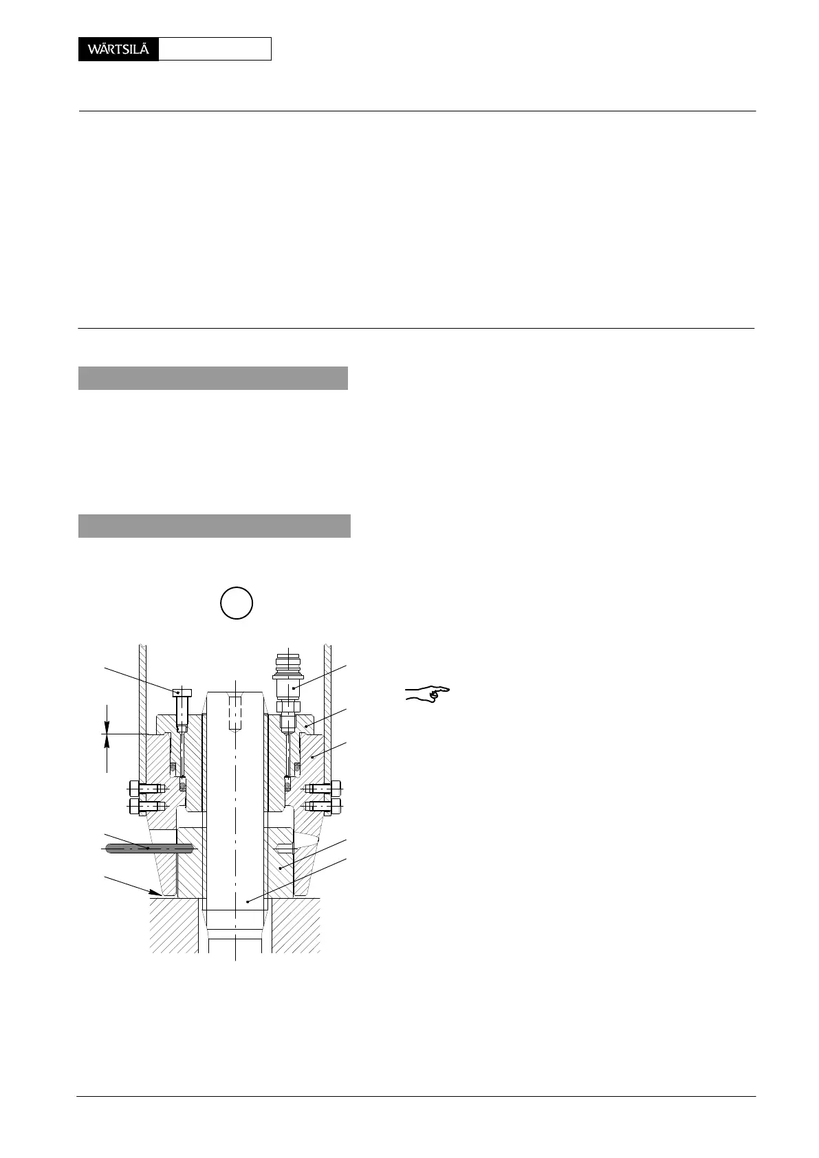
1 Hydr. tensioning device 94215 1 Cylinder cover stud
consisting of: 2 Nut
8 Pre-tensioning jacks 94215a 3 Vent screw
2 Connection pieces with HP hoses 94215b 4 Piston BN Limiting groove
1 Connection block 94934 5 Cylinder KO Slot
1 Hydr. distributor 94934a 6 Connection piece RS Round bar
3 HP hoses 94935 7 Sealing ring SA Gap
1 Hose 94935c
1 Hydraulic unit 94942
1. General
The instructions in 9403−4 concerning the application of hydraulic pre-tensioning
jacks for screwed fastenings must be followed.
Should a cylinder cover stud have to be replaced, please observe the indication in
2751−1.
2. Set-up of pre-tensioning jacks
⇒ Clean the threads of all cylinder cover studs
and the area around nuts 2.
Remark: Set-up of pre-tensioning jacks 94215
may be carried out either with opened vent screw
3 or by joining hose 94935c to connection piece
However, in the second case the squeezing o
must be collected in a receiver!
⇒ Place all pre-tensioning jacks on the cylind
cover studs and screw them down one by on
until there is only little or no clearance at ’x
⇒ Turn back the pre-tensioning jacks by abo
one turn (gap ’SA’).
A
012.963/05
x
3
RS
SA
6
4
5
1
2
ylinder Cover
oosening and Tensioning of Cylinder Cover Waisted Studs
2010