Maintenance
2751−1/A1
RT-flex50-D
Wärtsilä Switzerland Ltd
1/ 7
Tools: Key to Illustrations:
1 Dismantling tool 94008a−M56 1 Waisted stud 11 Distribution box
2 Pre-tensioning jacks 94252 2 Nut 12 Plug
1 Valve protector 94262 3 Vent screw 13 Strap
1 Suspension device 94265 4 Piston 14 Valve seat
1 Connection block 94934 5 Cylinder
1 Hydr. distributor 94934a 6 Valve spindle BN Limiting groove
2 Coupling elements 94934g 7 Valve cage KO Slot
3 HP hoses 94935 8 Expansion piece RC RUD-eye bolt
1 Hydraulic unit 94942 9 Protection pipe RS Round bar
10 Screw SA Gap
1. Removal
⇒ Drain cylinder cooling water from the respective cylinder (see 2708−1), and
close the air inlet to the air spring at the control air supply.
⇒ Remove all connected pipes. Removal of hydraulic piping see 8460−1.
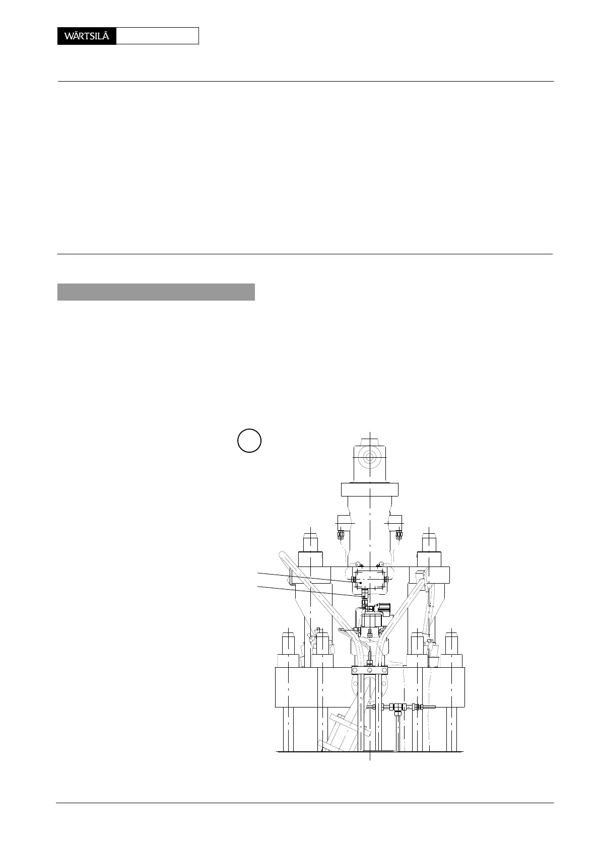
⇒ Disconnect plug 12 of the sensor cable from distribution box 11.
⇒ Loosen and remove expansion piece 8 (Fig. ’H’).
A
11
12
013.485/05
xhaust Valve
emoval and Fitting of Exhaust Valve, Replacing of Waisted Studs
2012-07