Maintenance
2138−1/A1
RT-flex50-D
Wärtsilä Switzerland Ltd
1/ 4
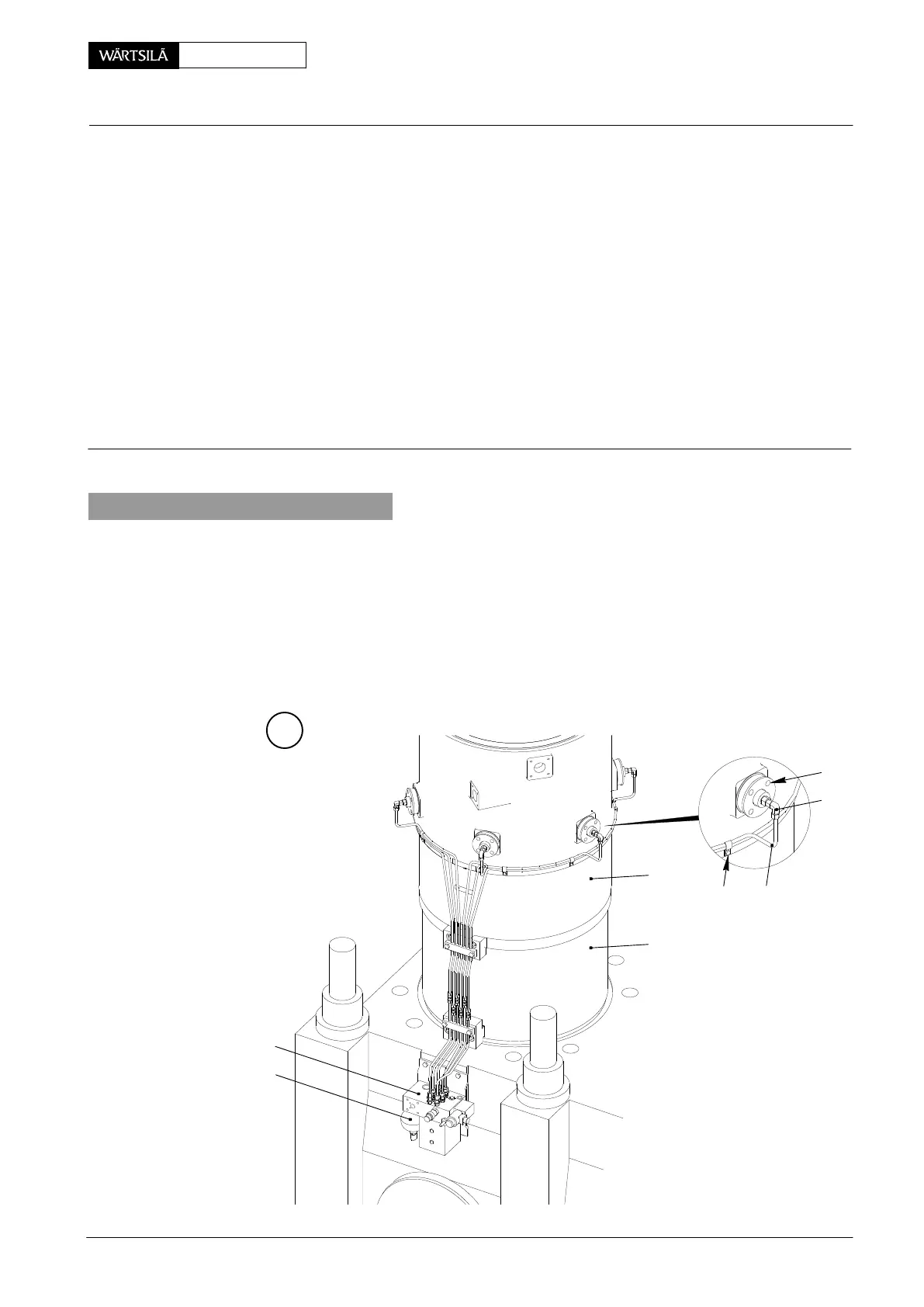
Tool: Key to Illustrations:
1 Tool box 94720c 1 Cylinder liner 14 Cu gasket
with fittings for charging 2 Lubricating pump 15 4/2-way solenoid valve
accumulator 3 Accumulator 16 Sink plunger
1 HP oil pump 94931 4 Water guide jacket (lower part) 17 Pin (tool)
1 Hydr. distributor 94934h 5 Lubricating quill 18 Shut-off valve servo oil
(with pr. gauge 0...25 bar) 6 Screwed union 19 Venting valve servo oil
1
Connection nipple (G¼”)
94934i 7 Non-return valve 20 Venting valve lube oil
1 HP hose 94935 8 Bush 21 Pipe bracket
9, 9a Flange 22 O-ring
10 Joint
11 Screw
12 Adjustable angle union
13 Lubricating oil pipe DF Sealing surface
1. General
If only the lubricating quill must be removed, with water guide jacket (lower part) in
situ, then bush 8, flanges 9 and 9a may remain in place. Therefore, the cylinder
cooling water must not be drained.
In order to remove a water guide jacket (lower part) 4 or cylinder liner 1 however, all
lubricating quills and bushes must be dismantled, whereby the cylinder cooling
water must be drained on the relevant cylinder (see 2708−1 ’Removal of cylin-
der cover’).
A
2
3
11
12
21 13
4
1
ubricating Quill
emoval and Fitting with Pulse Feed Lubricatio
CLU4−C / 2011-12