Maintenance
5552−3/A1
RT-flex50-D
Wärtsilä Switzerland Ltd
1/ 1
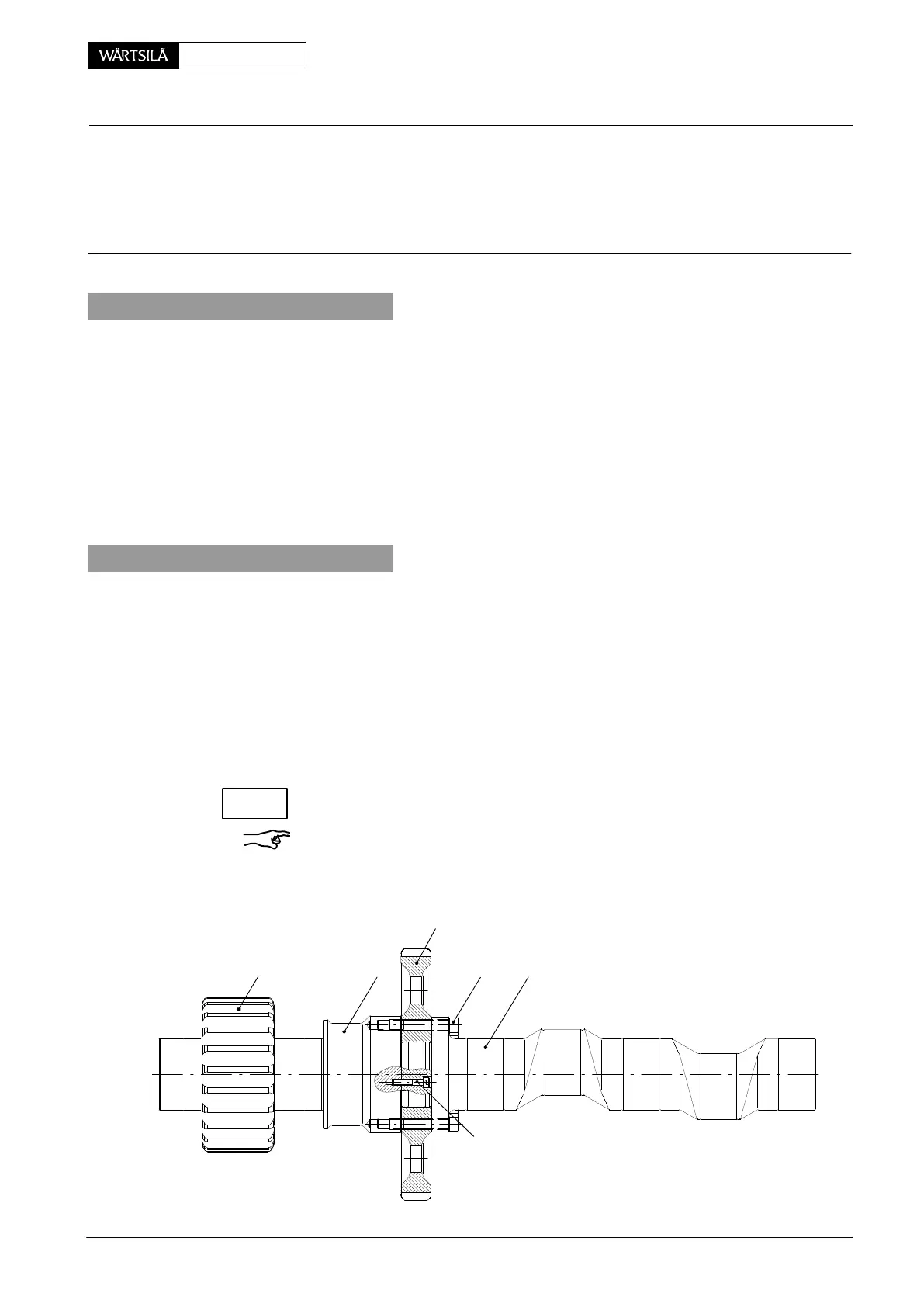
Key to Illustration:
1 Camshaft 4 Gear wheel
2 Gear wheel 5 Head screw
3 Shaft 6 Head screw
1. Removing
The camshaft must be removed from the supply unit for removing and fitting the
gear wheel 2 (see 5552−2).
It is recommended to put camshaft 1 and shaft 3 on suitable wooden underlays to
be able to work appropriately.
⇒ Loosen head screws 5 and withdraw camshaft 1 from gear wheel 2 using two
jacking screws M10.
⇒ Loosen head screws 6 and withdraw gear wheel 2 from shaft 3 using two jack-
ing screws M10.
2. Fitting
All parts must be clean and in perfect condition.
⇒ Oil the mating surfaces of gear wheel 2 and shaft 3.
⇒ Push gear wheel 2 carefully onto shaft 3 and fasten it with head screws 6.
⇒ Oil the mating surfaces of camshaft 1 and gear wheel 2.
⇒ Oil the threads and seating surfaces of head screws 5.
⇒ Join carefully camshaft with gear wheel 2 and fasten it with head screws 5.
⇒ Tighten the head screws crosswise and equally up to a torque of 200 Nm.
No clearance must be at hand between gear wheel 2 and shaft 3.
Remark: After a replacement of gear wheel 4 and shaft 3, the running and back-
lash clearances and performance of the teeth must be checked (see 4103−1).
013.058/05
6
31
2
4 5
upply Unit
emoving and Fitting the Gear Wheel on Camshaft
2010
CHECK