Maintenance
1132−2/A1
RT-flex50-D
Wärtsilä Switzerland Ltd
13/ 17
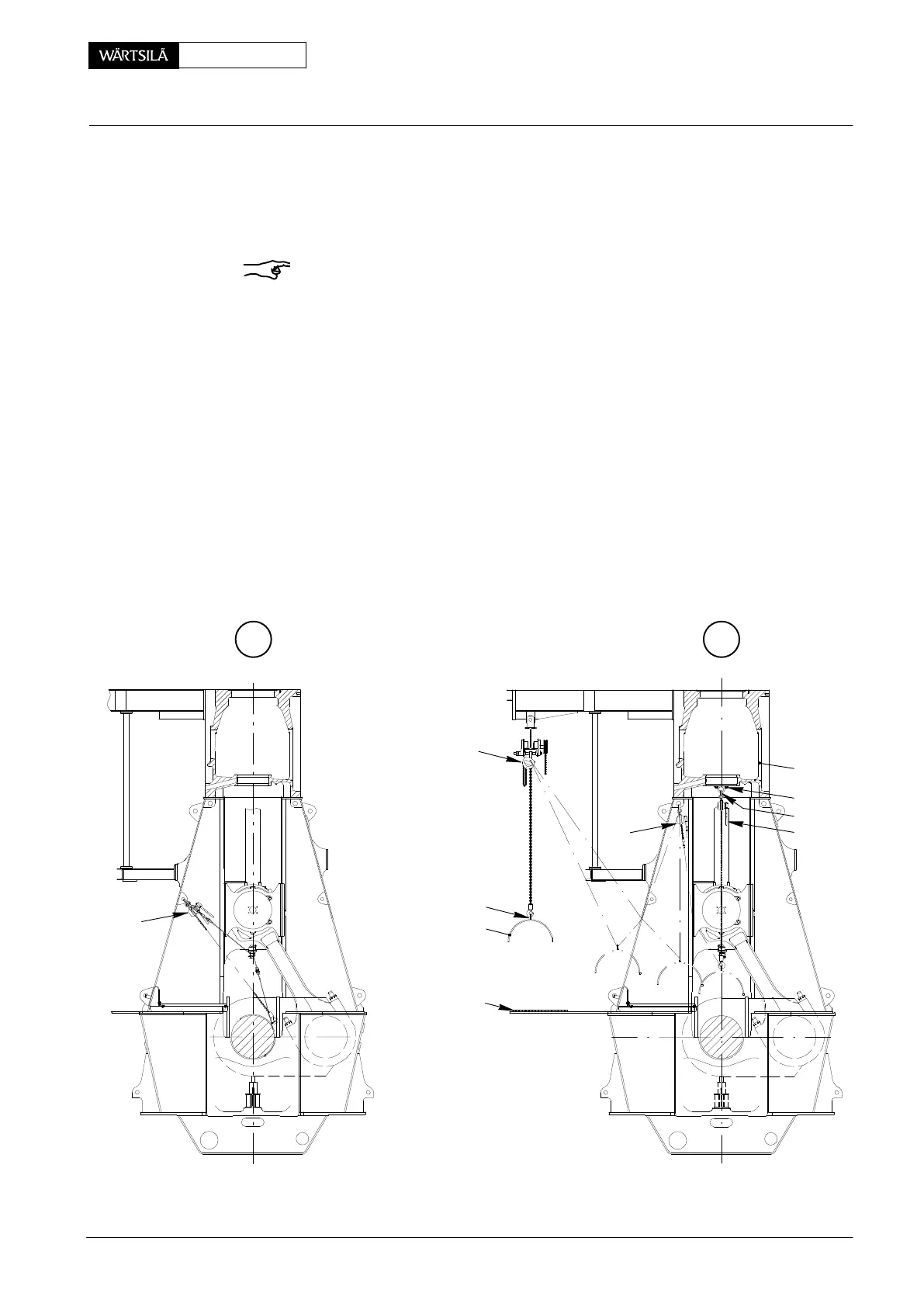
⇒ Remove assembling and dismantling device 94117, rope 94120a, device
94119b and turning-out device 94118a.
⇒ Fasten transportation tool 94116a to bearing shell 4a and turn it completely
out without major effort by means of manual ratchet H
1
.
Remark: When retracted in upper position, both bearing shell ends are distinctly
uplifted from the bearing journal (see detail with gap ’x’ in Fig. ’J
2
’).
Also make sure that both ends of the bearing shell are cleared from the bearing
girder!
⇒ Fasten lifting ring 94332 (with shackle 94332a) to cylinder block 14 using
screws 15 which must be tightened with a torque of 200 Nm (see detail Fig.
’D’).
⇒ Connect manual ratchet H
2
to shackle 94332a and the transportation tool.
⇒ Carefully lift the bearing shell while guiding it manually, slacken manual ratch-
et H
2
and take over bearing shell with H
3
.
⇒ Detach manual ratchets H
1
and H
2
.
⇒ Remove the bearing shell from the crankcase using manual ratchet H
3
and
spur-geared chain block ’HZ’.
⇒ Place the bearing shell on wooden underlay ’HU’ on the bottom plate.
L
1
94332
H
1
L
2
018.609/09 018.613/09
H
2
H
3
HZ
94116a
4a
14
94332
HU
50−D / 2010
Removal and Fitting of a Main Bearing