Maintenance1224−1/A1 RT-flex50-D
Wärtsilä Switzerland Ltd
2/ 6
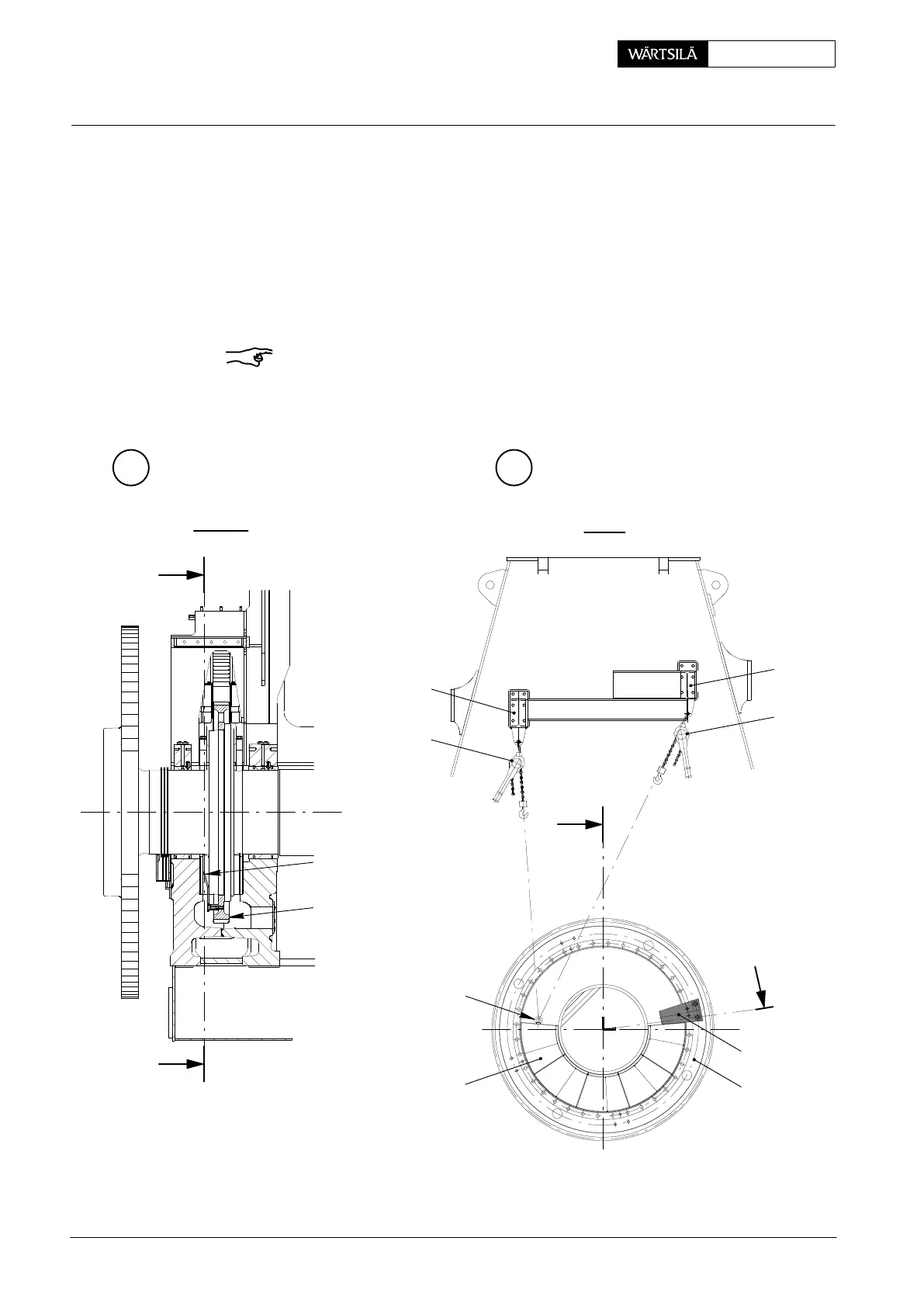
⇒ Screw RUD-eye bolt ’RC’ into thrust bearing pads 5 or 5a to be removed.
⇒ Fasten lifting tackles ’HZ’ to the straps of supports 7 and connect them with
ropes ’a’ and ’b’ to RUD-eye bolt ’RC’.
⇒ Insert and laterally fasten turning-out device 94155 (for engines with a 1-part
gear wheel 6) or turning-out device 94155a (for engines with a 2-part gear
wheel 6) as shown in Fig. ’B’.
⇒ The crankshaft is then to be turned with the turning gear pushing the pads out
which can then be lifted up and removed one by one as shown in Fig. ’C’.
Remark: When only a few thrust bearing pads of a row are to be removed the
crankshaft is located in its axial position by the remaining pads. When all thrust
bearing pads must be removed then the crankshaft must be prevented from sliding
axially. Therefore, insert a piece of hardwood of the same thickness in place of the
thrust bearing pad.
B C
I
I
6
I - I
II - II
012.959/05
012.960/05
II
II
a
b
5, 5a
RC
HZ
7
6
7
94155
94155a
94155
94155a
HZ
2010
Removal and Fitting the Thrust Bearing Pads