Maintenance
2124−2/A1
RT-flex50-D
Wärtsilä Switzerland Ltd
7/ 9
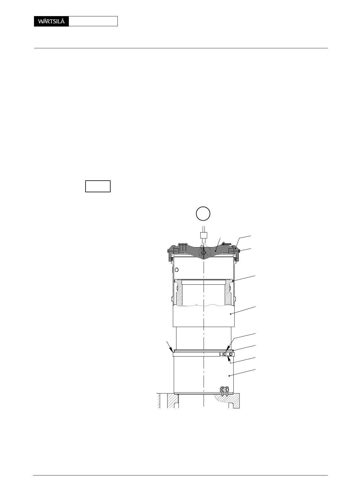
4.2 Fitting
D Holders 16 and 16a must be fitted to the cylinder liner as shown in Fig. ’F’.
D Lifting gear 94202 must be placed according to paragraph 2.1.
⇒ Clean sealing and seating surfaces ’AF’.
⇒ Place new O-rings 18 of the specified quality and dimension into the grooves
on the cylinder liner. Smear O-rings and corresponding sealing surfaces of
cylinder guide jacket 3 with lubricating oil.
⇒ Move the water guide jacket above the cylinder liner, slowly lower and align it
to ensure that centring pin 14a fits into the corresponding bore on fuel side.
⇒ Fit connection pieces 9 and transition tubes 8 to water guide jacket 3 (Fig. ’B’
view II-II).
⇒ Fit all lubricating quills and connect the their pipings.
Actuate the cylinder lubricating pump until oil emerges from all the lubricating
bores in the corresponding cylinder liner (see 2138−1 ’Function check’).
G
012.890/05
3
14a
18
16a
2
AF
18
94202 94202g
94202h
50−D / 2010
Removal and Fitting of Cylinder Liner or Water Guide Jacket
CHECK