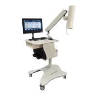
CAPINTEC, INC. CAPTUS
®
4000e
4-2 GENERAL SETUP November 16
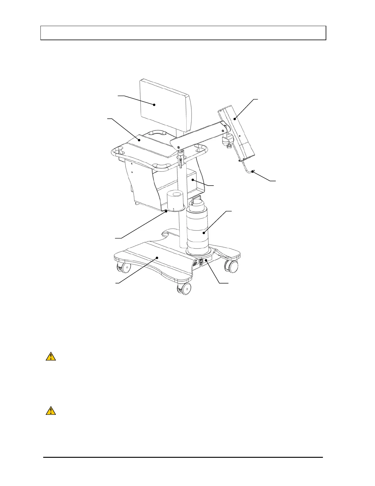
If your system includes a Floor Stand, installation consists of placing the components on the
Stand and securing them in place as shown in Figure 4-1.
Figure 4-1 Complete Assembly with Floor Stand
If your system includes a Table Top Stand, installation consists of placing the components on
a sturdy table or bench.
CAUTION: Only the included USB devices should be connected to the USB ports on
the Computer. If any USB devices other than the models supplied by
Capintec are used, the safety of the unit may be compromised or other
devices located in the same general area as the CAPTUS
®
4000e may
become susceptible to EMI. The maximum Input/Output voltages are
CAUTION: Do not attach a Monitor to the VGA port on the rear of the Computer. If a
Monitor is attached to this port, the safety of the unit may be
compromised or other devices located in the same general area as the
®
4000e may become susceptible to EMI.
Collimator with
Probe Detector
Transformer
Stand
Touch Screen
Computer