4.15 Electroluminescent (EL) Central Processing Unit (CPU) P.C. Board, EL Display Faceplate, and
EL Display
Chapter 4: Removal, Replacement, and Adjustment Procedures
Isolette® Infant Incubator (Model C2000) Service Manual Page 4 - 43
4
4.15 Electroluminescent (EL) Central Processing Unit (CPU) P.C.
Board, EL Display Faceplate, and EL Display
Tools required: Phillips head screwdriver
Removal
1. Remove the controller assembly from the unit (refer to procedure
4.4 on page 4-11).
2. Remove the electroluminescent (EL) display front panel assembly
from the controller assembly (refer to procedure 4.14 on page 4-41).
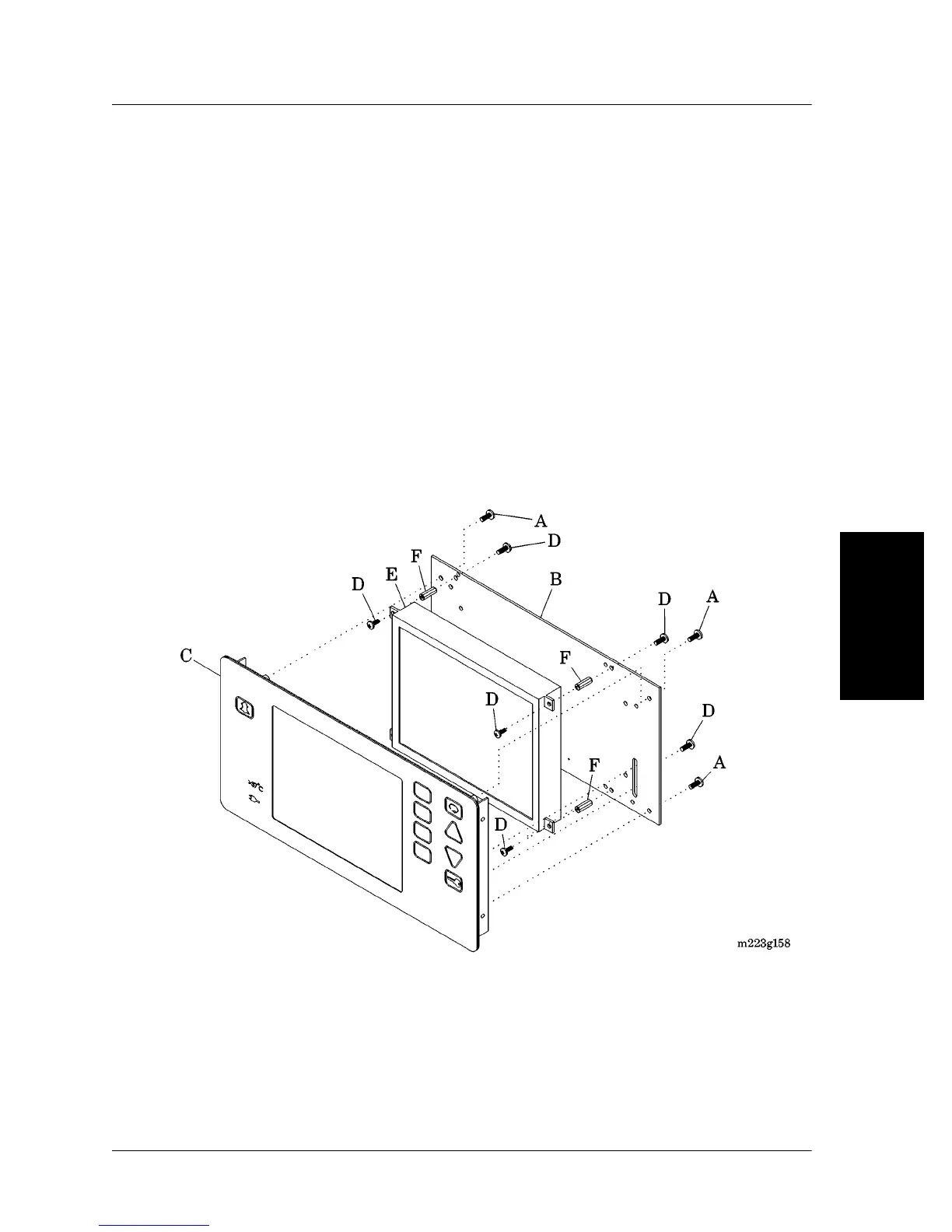
3. Remove the four screws (A) that secure the EL central processing
unit (CPU) P.C. board (B) to the EL display faceplate (C) (see figure
4-20 on page 4-43).
Figure 4-20. EL CPU P.C. Board and EL Display
4. Remove the EL CPU P.C. board (B) from the EL display faceplate
(C) (see “Component Handling” on page 6-8).
5. Remove the eight screws (D) that secure the EL display (E) to the
EL CPU P.C. board (B).