4.17 Interface/Power Supply Module
Chapter 4: Removal, Replacement, and Adjustment Procedures
Isolette® Infant Incubator (Model C2000) Service Manual Page 4 - 47
4
4.17 Interface/Power Supply Module
Tools required: Phillips head screwdriver
Removal
1. Remove the controller assembly from the unit (refer to procedure
4.4 on page 4-11).
2. Remove the EL display front panel assembly from the controller
assembly (refer to procedure 4.14 on page 4-41).
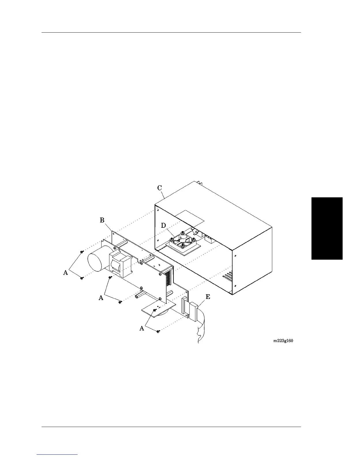
3. Remove the six screws (A) that secure the interface/power supply
module (B) to the controller assembly (C) (see figure 4-22 on page
4-47).
Figure 4-22. Interface/Power Supply Module
4. Disconnect the fan assembly (D) from the interface/power supply
module (B).
5. Remove the interface/power supply module (B) from the controller
assembly (C).