Chapter 4 Disassembly/Assembly and Adjustment
4.2 Disassembly/Assembly
4-11
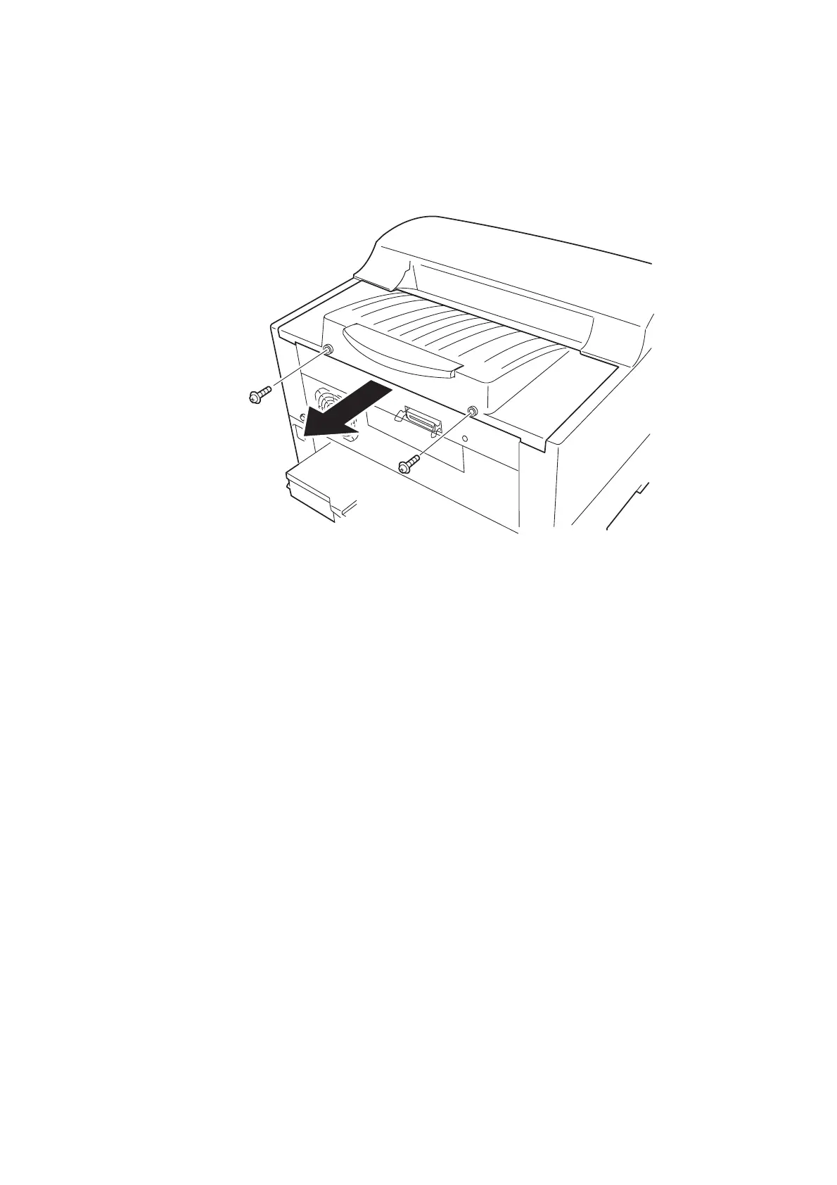
REP1.7 (SCC) COVER ASSY STACK CL (PL1.1.22)
<Removal>
1) Remove the two screws (gold, with washer, 8mm) securing the COVER ASSY STACK CL and
remove the COVER ASSY STACK CL.
<Replacement>
Perform the removal procedures in the reverse order.
1)-1
1)-1
1)-2
AZS411CA
 Loading...