Chapter 4 Disassembly/Assembly and Adjustment
4.2 Disassembly/Assembly
4-19
REP3.2 FRAME ASSY ROLL FEED (TRAY) (PL3.1.10)
<Removal>
1) Remove the CASSETTE ASSY 250 CL from the printer.
2) Remove the FRAME BASE RTD TRAY HN. (Refer to REP 3.5)
3) Open the TRAY ASSY FRONT CL (PL3.2.1).
4) Remove ROLL FEED ASSY TRAY. (REP3.4)
5) Pull the LEVER FRONT R (PL8.1.11) and the LEVER FRONT L (PL8.1.12) toward you, open the
COVER ASSY FRONT.
6) Remove the COVER ASSY STACK CL. (REP1.7)
CAUTION
Be careful not to damage the FFC OPP CL (PL1.1.21) in the procedure
below.
7) Remove the COVER ASSY TOP CL with the FFC OPP CL. (REP1.4)
8) Remove the COVER SIDE LEFT CL. (REP1.1)
9) Remove the COVER ASSY RIGHT CL. (REP1.2)
10) Remove the COVER FRONT LEFT. (REP3.7)
11) Remove the COVER FRONT RIGHT. (REP3.6)
12) Remove the TRAY ASSY FRONT CL. (REP3.8)
13) Remove the FRONT UNIT. (REP3.1)
14) Remove the FRAME ASSY FRONT. (REP8.6)
15) Remove the CLUTCH ROLL FEED (TRAY). (REP3.3)
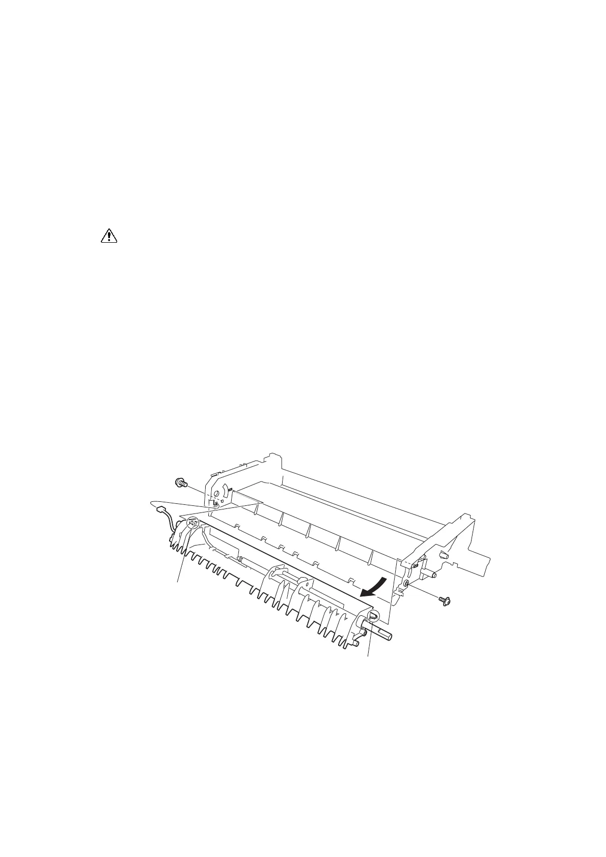
16) Remove the three screws (gold, with flange, tap, 8mm) securing the FRAME ASSY ROLL FEED
(TRAY), remove the right side convex of the FRAME ASSY ROLL FEED (TRAY), and then remove
it to the arrow direction.
<Replacement>
Perform the removal procedures in the reverse order.
Tab
Tab
AZS485CA
16)-1
16)-1
16)-2
 Loading...