NOTE
NOTE
・The voltage axis range for each channel is set.
・The set value denotes the voltage value for 1 DIV along the voltage axis
(vertically).
・When waveform data is out of range limit, that waveform portion is displayed
in another color in the display window.
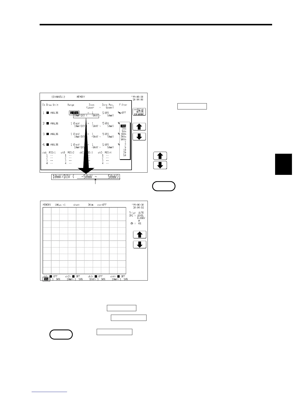
Method 1 Screen: CHANNEL 1, DISPLAY
1. Call up the CHANNEL 1 or DISPLAY screen.
2. Use the
CH SELECT key to open selected
channel screen.
3. Move the flashing cursor to the point shown in
the figure on the left.
4. Use the JOG control or the function keys to
make the selection.
: Move the cursor up in the selection window.
: Move the cursor down in the selection
window.
・On the DISPLAY screen, the selection window
is not displayed.
・When out of range, waveform may not appear
even if it is indicated within the range based
on zero position settings.
Method 2 Screen: CHANNEL 1, DISPLAY
1. Use the CH SELECT key to open selected channel screen.
2. Press the
INPUT RANGE key to set the range for each channel.
・The
INPUT RANGE key can be used regardless of where the flashing cursor
is located, if the selected channel is displayed on the CHANNEL 1 or
DISPLAY screen.
・If the variable function is enabled, the size of a waveform on the screen does
not change, even if the voltage axis range is changed.