19
────────────────────────────────────────────────────
2.4 Probe Connection
────────────────────────────────────────────────────
.4.1 8936 ANALOG UNIT, 8938 FFT ANALOG UNIT and
8946 4 ch ANALOG UNIT
WARNIN
Never connect the probe to the 8835-01 while the probe is already
connected to the measurement object. Otherwise there is a risk of
electric shock.
Use only the specified connection cables. An insulated BNC connector
is used for the specified connection cables to prevent electric shock. If
a metal BNC connector is used, electric shock may result, as the input
L-terminal and the metal part of the BNC connector will have the same
potential.
CAUTIO
When disconnecting the BNC connector, be sure to release the lock before
pulling off the connector. Forcibly pulling the connector without releasing the
lock, or pulling on the cable, can damage the connector.
NOTE
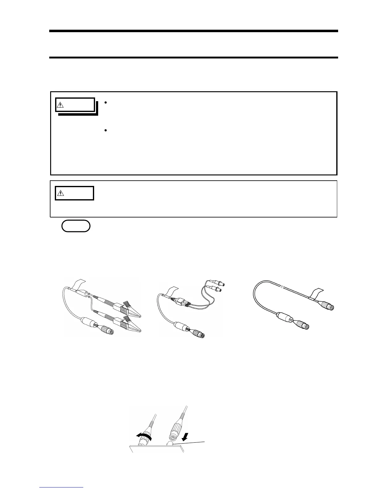
9197 CONNECTION CORD
(Maximum input voltage: 500 V)
9198 CONNECTION CORD
(Maximum input voltage: 300 V)
9217 CONNECTION CORD
(Maximum input voltage: 300 V)
Connector ridg
.4 Probe Connection
Use only the specified connection cables. Using a non-specified cable may
result in incorrect measurements due to poor connection or other reasons.
In addition, the BNC connector may be damaged.
For analog input connection, use optional 9197, 9198 CONNECTION CORDs.
Use of any other cables may result in risk of electric shock.
For connecting 8946, use 9198 CONNECTION CORD.
Connecting to the main unit
1. Align the BNC connector with the guide groove of the unit input connector,
and turn clockwise while pressing in to lock the connector.
2. To remove from the unit, turn the BNC connector counterclockwise to release
the lock, then pull it.