57
────────────────────────────────────────────────────
4.2 Making Settings
────────────────────────────────────────────────────
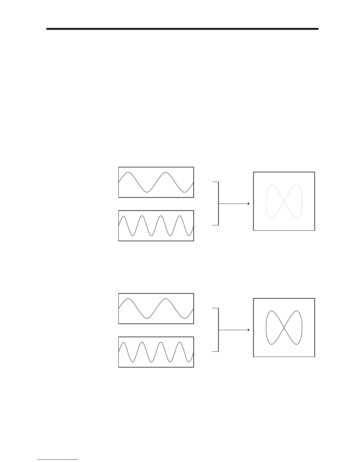
・Setting the display format to X-Y in Section 4.2.4 allows X-Y waveforms to be
combined.
・Assign any analog channel to the X axis and the other seven channels to the Y
axis to form the combined plot.
・Voltage axis magnification/compression is active also when using X-Y
combined plotting.
・Using the A/B cursors, it is possible to specify the data between the cursors for
partial plotting.
(1) X-Y (dot)
・The sampled data is displayed and recorded just as it comes.
・Linear interpolation is not performed.
(2) X-Y (line)
・Linear interpolation is performed.
・The display becomes easier to read, but display speed is slower compared to
dot display.