42
────────────────────────────────────────────────────
3.2 Basic Measurement and Setting Procedures
────────────────────────────────────────────────────
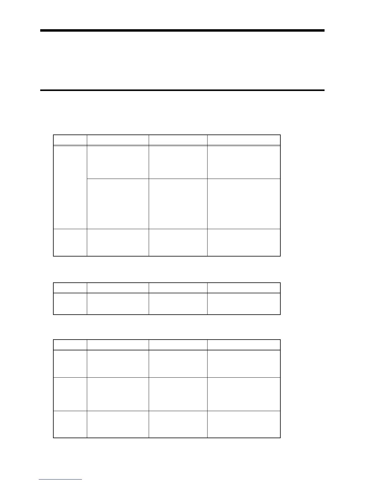
.2.1 Basic Operation Flow
Panel ke
Setting screen Setting item Description
STATUS Status 1 Time axis
Recording length
Format
Printer format
etc.
Sets data capture
conditions (see chapters
on various functions).
Various
settings
Status 2 Trigger mode
Pre-trigger
Trigger source
External trigger
Analog trigger
Logic trigger
Timer trigger
etc.
Sets the triggers (see
Chapter 8).
CHAN Channel Voltage axis range
Input coupling
Low pass filter
etc.
Sets the voltage axis
range, input coupling, and
filter (see chapters on
various functions).
Panel ke
Setting screen Setting item Description
START Starts data capture. Waveform
data
capture
Panel ke
Setting screen Setting item Description
SELECT
key
Display Cursor type
Cursor movement
etc.
Uses the cursor to read
measurement values (see
Chapter 11).
Viewing/
storing
waveform
data
DISP Display Select waveform
Magnification ratio
along the vertical/
horizontal axis
etc.
Sets the magnification
ratio for waveform data
(see chapters on various
functions).
FILE FD, PC card Store file type
Store range
Comment
etc.
Stores waveform data
(see Chapter 13).
.2 Basic Measurement and Setting Procedures
This section uses some representative examples to describe basic measurement
steps and settings.
The basic operation flow is shown below.
↓
↓