23
────────────────────────────────────────────────────
2.4 Probe Connection
────────────────────────────────────────────────────
To avoid electrical accidents, make sure that the MEMORY HiCORDER
and the equipment being measured are powered off before making
connections. Do not make connections with the power turned on.
When using the 9318 or 9319 CONVERSION CABLE, there is no isolation
between GND the MEMORY HiCORDER and GND of the clamp on
sensor/probe. Exercise extreme care in connection to avoid possible
damage to the equipment or personal injury.
When connecting 8940 F/V UNIT to 3273 or 3273-50, and conductors
being measured carry in excess of the safe voltage level (SELV-E) and
not more than 300 V, to prevent short circuits and electric shock while
the core section is open, make sure that conductors to be measured
are insulated with material conforming to (1) Overvoltage Category l
, (2)
Double Insulation (Reinforced insulation) Requirements for Working
Voltage of 300 V, and (3) Pollution Degree 2. For safeties sake, never
use this sensor on bare conductors. The core and shield case are not
insulated.
When connecting 8940 F/V UNIT to 3273 or 3273-50, do not damage
insulation sheathing on testing device.
Refer to the following standards regarding the meanings of underlined
terms. IEC 61010-1, IEC 61010-2-031, IEC 61010-2-032
WARNIN
When using the clamp-on sensor or clamp-on probe, be sure to use the
optional 9318 or 9319 CONVERSION CABLE.
CAUTIO
・When disconnecting the BNC connector, be sure to release the lock before
pulling off the connector. Forcibly pulling the connector without releasing the
lock, or pulling on the cable, can damage the connector.
・When using the Model 3273-50 with the 8940, bear in mind that the
maximum input of the 3273-50 is 15 Arms. Exceeding this measurement
level could damage the instrument.
Connection cable connection (Frequency, count, pulse duty ratio and voltage measurement)
Use the optional 9198 CONNECTION CORD for
connection to the F/V UNIT.
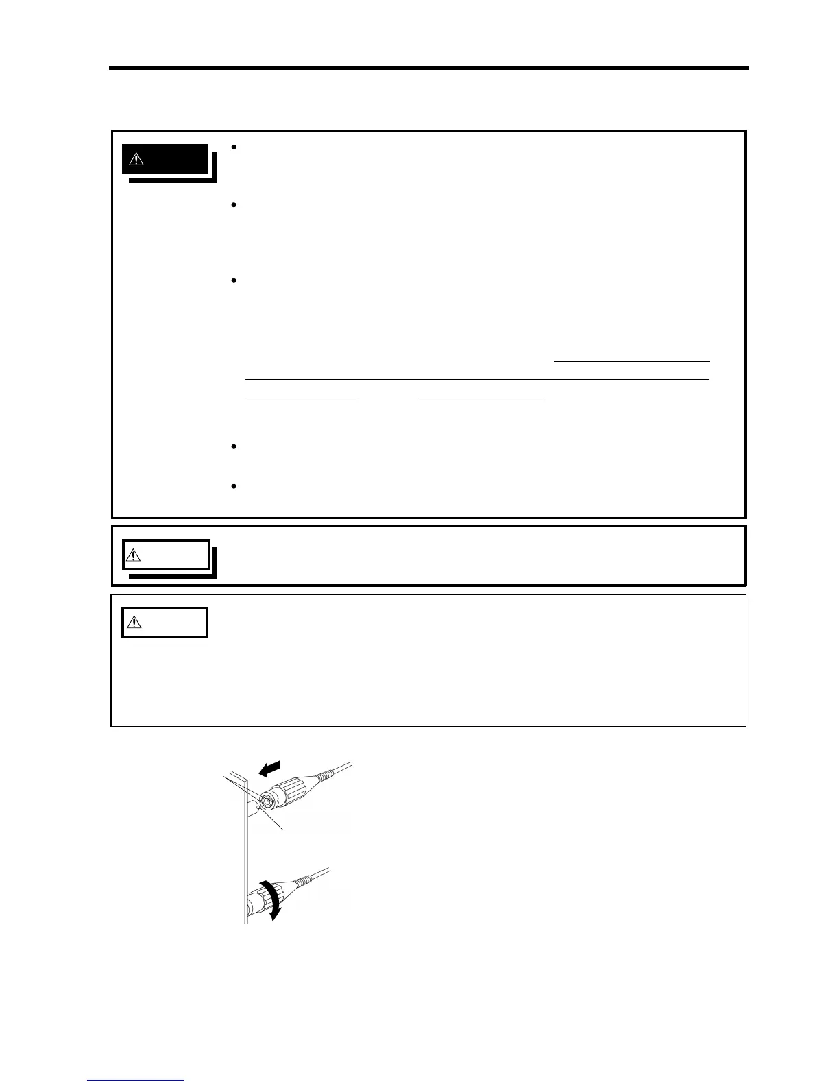
1. Align the BNC connector with the guide groove of the
8826 input connector, and turn clockwise while pressing
in to lock the connector.
2. To remove from the unit, turn the BNC connector
counterclockwise to release the lock, then pull it.
Clamp connection (Current measurement)
The following clamp-on sensors and clamp-on probes can be connected using
the 9318 and 9319 CONVERSION CORDs.
9318:9270, 9271, 9272, 9277, 9278, 9279, 9319:3273
 Loading...


