996 Matrix ETERNITY NE System Manual
• Now, configure the Peer-to-Peer Table.
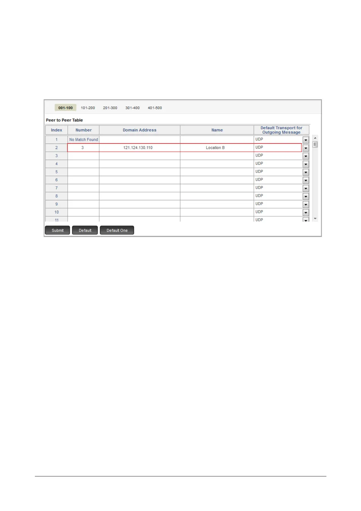
The Peer-to-Peer table stores up to 500 entries. Each entry consists of the parameters—Number,
Domain Address, Name, Default Transport for Outgoing Message.
At location A, you would have to configure the Peer-to-Peer table as follows:
• In the Number column of the Peer-to-Peer table, enter the digit you configured as Route Code in
the CUG Table for calling the extension numbers of the PBX at Location B. In this case ‘3’.
•In Domain Address, enter the IP Address of the WAN Port of the Router at Location B.
•In Name, enter ‘Location B’ for identification.
• Keep Default Transport for Outgoing Message as ‘UDP’.
• At Location B, you may do a suitable configuration of the PBX.
• When an extension user 201 of SARVAM UCS at Location A dials 301, an extension number of PBX B, the
system checks the CUG table to match the dialed digits with the Route Code and the Dialed Digit Count.
As a match is found, it selects the SIP trunk defined for routing the Route Code, i.e. SIP 1.
• As SIP 1 is set to Peer-to-Peer mode, the system checks the Peer-to-Peer Table configured. It finds a
match for the digit ‘3’ and will route the call to the IP Address configured for this number. In this case, to the
IP Address of the Router at Location B (121.124.130.110).
• Further, the Router will forward the call to the PBX B. With suitable configuration done in PBX B, the call
will be routed to the desired destination i.e. extension 301.
How to configure
For instructions on configuring the SIP Trunk for the Peer-to-Peer application—SIP Trunk Mode, SIP ID, Treat
incoming calls as Station, Trusted IP Address/es table—see “SIP Trunks”.


 To Next Page