DMTA-10045-01EN, Rev. E, August 2016
Applications
125
3. Set the probe tips over a good area of the standard, and then press the CAL NULL
key ( ).
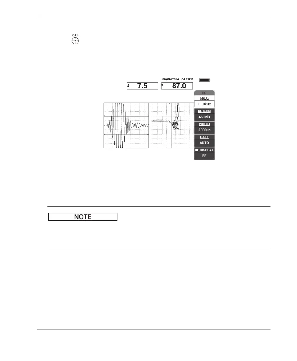
4. Scan over the far-side and near-side disbonds, and then, while you keep the probe
moving over the disbonds, ensure that both defects are detected (see Figure 6-4 on
page 125).
Figure 6‑4 Detecting the far‑side and near‑side disbonds
GATE setup
By default, the GATE is set to AUTO. In AUTO mode the BondMaster 600
automatically detects the peak signal from the RF view and uses it to construct the XY
flying dot view.
5. If desired, manually set the gate to the desired position by pressing GATE (D key)
and rotating the knob.
A recommended GATE position would be the peak of the first reflection.
The recommended GATE position is often to the left of the first strongest signal
peak (see Figure 6-5 on page 126).