DMTA-10045-01EN, Rev. E, August 2016
Appendix A
212
Table 10 on page 212 describes all the connections available on the 15-pin I/O
connector. Table 11 on page 212 describes all the connections available on the
VGA OUT 15-pin connector.
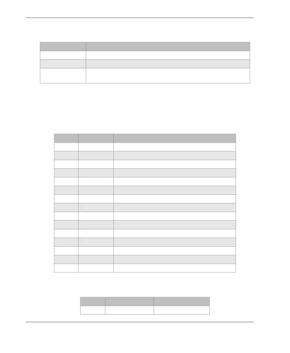
Table 9 Input/output specifications
Parameter Va lue
USB One USB 2.0 peripheral port
Video output One standard VGA analog output port
Input/output One 15-pin I/O port (male) with 6 analog outputs, 4 alarm outputs
(which can become inputs), and 2 encoder signals (future expansion)
Table 10 BondMaster 600 Input/Output 15‑pin I/O connector
Pin Signal Description
1 AOUT_1 Analog Output 1
2 AOUT_2 Analog Output 2
3 AOUT_3 Analog Output 3
4 AOUT_4 Analog Output 4
5 AOUT_5 Analog Output 5
6 AOUT_6 Analog Output 6
7GNDGround
8 VDD +5 V voltage
9 ENCD_INT Encoder Interrupt (future expansion)
10 ENCD_DIR Encoder Direction (future expansion)
11 GND Ground
12 HW_IO_1 Hardware I/O 1: Alarm Output 1, Generic Input 1
13 HW_IO_2 Hardware I/O 2: Alarm Output 2, Generic Input 2
14 HW_IO_3 Hardware I/O 3: Alarm Output 3, Generic Input 3
15 HW_IO_4 Hardware I/O 4: Alarm Output 4, Generic Input 4
Table 11 BondMaster 600 VGA 15‑pin port output
a
Pin Signal Description
1 VGA_RED VGA red output