DMTA-10045-01EN, Rev. E, August 2016
Chapter 2
46
Do not allow metallic or foreign objects to enter the device through connectors or any
other openings. Otherwise, an electric shock or malfunction may result. To avoid the
risk of an electric shock, do not touch the inner conductors of the PROBE connector.
Up to 80 V can be present.
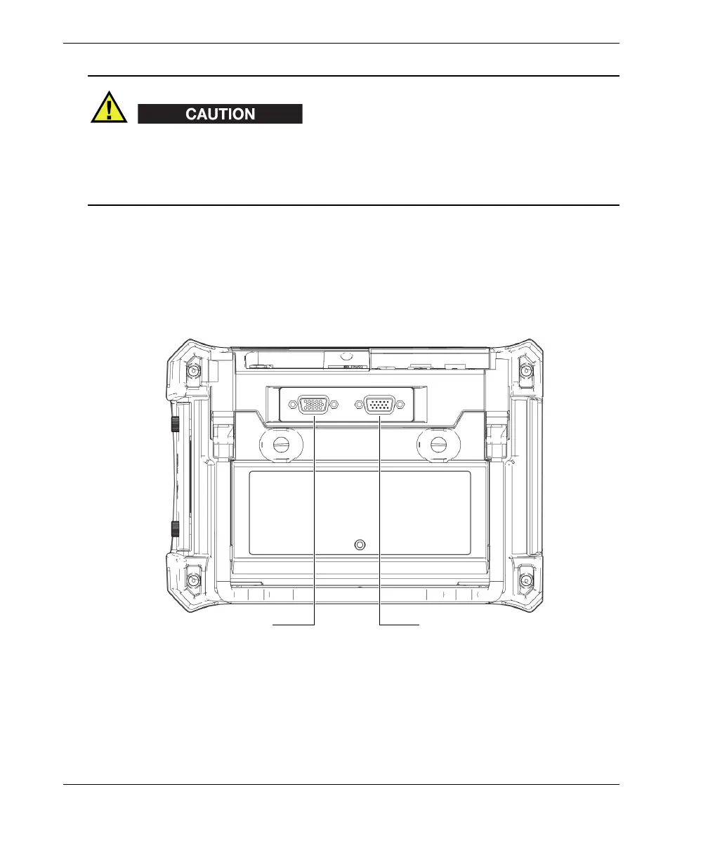
2.5.2.2 Input/Output and VGA OUT Connectors
The input/output (I/O) and the VGA OUT connectors are located at the back of the
BondMaster 600, in the upper section (see Figure 2-21 on page 46). A rubber cover
protects each connector.
Figure 2‑21 The VGA OUT and I/O connectors
VGA OUT connector
I/O connector