DMTA-10045-01EN, Rev. E, August 2016
Applications
145
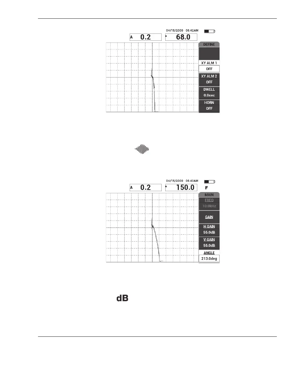
Figure 6‑32 The scan over the disbond and repaired area
7. Press the MAIN menu key ( ), then press ANGLE (E key) and adjust the
signal angle so that the disbond signal points upwards at 90° (see Figure 6-33 on
page 145).
Figure 6‑33 Adjusting the signal angle upwards
8. Press the GAIN key ( ), and then adjust the signal amplitude so that the
disbond signal extends to about 4 divisions away from the null position
(crosshairs) [see Figure 6-34 on page 146].