DMTA-10045-01EN, Rev. E, August 2016
Overview of the BondMaster 600
25
delamination are present. Any changes in the part's mechanical impedance are
reflected in the amplitude and phase displayed on the instrument screen. Resonance
mode is typically used to detect metal-to-metal disbonds and interply delaminations.
In carbon fiber or fiberglass composites, the location of the defect can often be
estimated using the phase deflection on the instrument screen.
2.2 Connectors
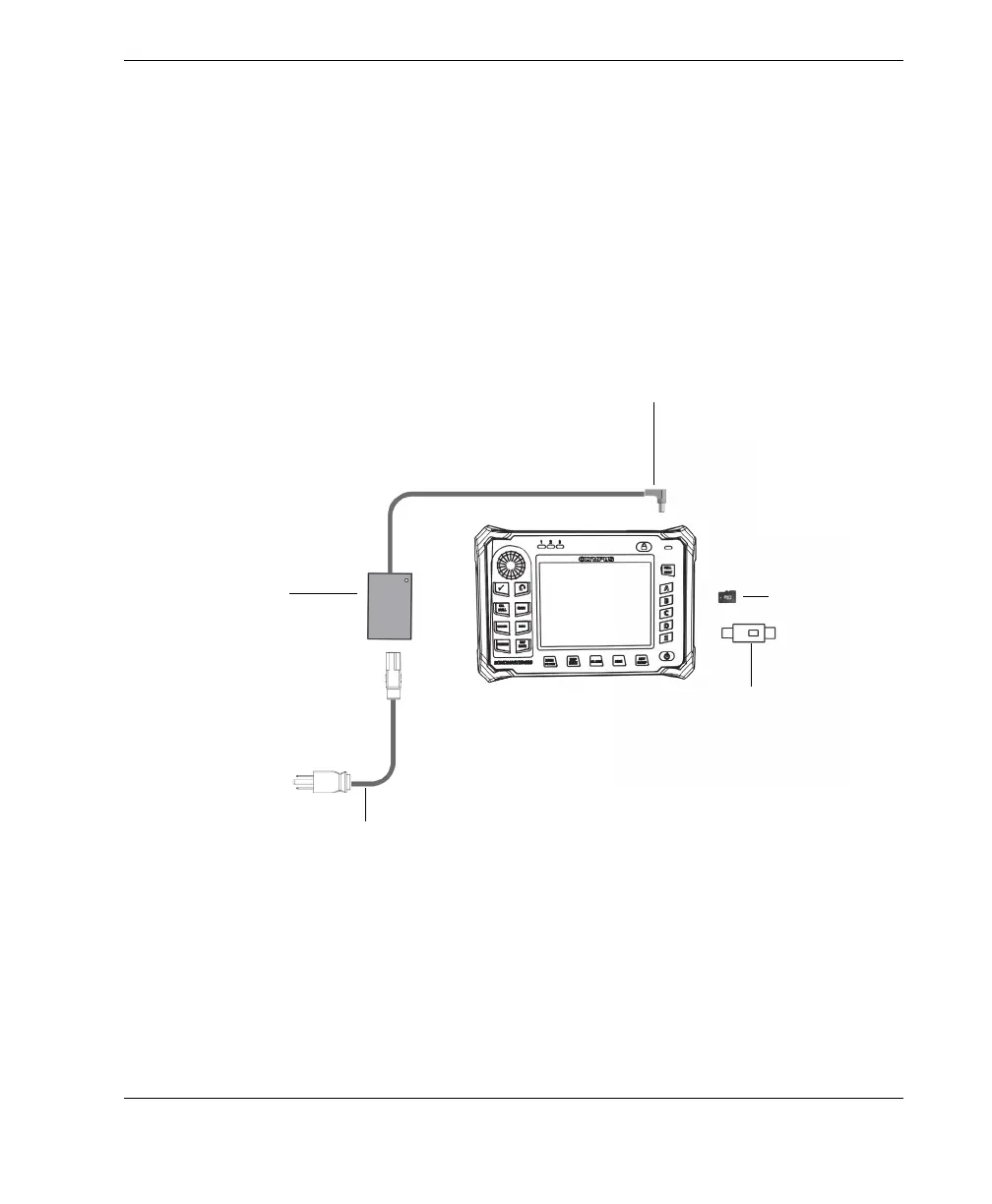
Figure 2-1 on page 25 illustrates the connections of the BondMaster 600 with the
charger/adaptor, the microSD card, and a personal computer (PC).
Figure 2‑1 The BondMaster 600 connections
To power
outlet
DC power plug
EP-MCA-X
charger/adaptor
AC power cord
USB to PC
microSD card