Raisecom
iTN2100 (P100R002) Hardware Description
Raisecom Technology Co., Ltd.
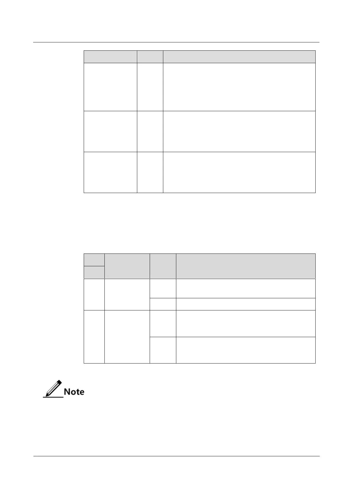
Primary/Slave LED for the aggregation card
In dual-card protection mode:
Green: the card is primary.
Off: the card is slave.
In non-protection mode: it is Green.
LOF alarm LED
Red: input LOF alarms are generated on optical
interfaces 1, 2, 3, and 4.
Off: no input LOF alarms are generated on optical
interfaces 1, 2, 3, and 4.
LOS alarm LED
Red: input LOS alarms are generated on optical
interfaces 1, 2, 3, and 4.
Off: no input LOS alarms are generated on optical
interfaces 1, 2, 3, and 4.
13.9.5 DIP switches
Table 13-45 lists configurations of the DIP switch on the iTN2100-EOT-GESTM4.
Table 13-45 Configurations of the DIP switch on the iTN2100-EOT-GESTM4
Set the optical
interface rate.
Set the rate of the first optical interface to STM-4;
others become invalid.
Set the rate of the four optical interface to STM-1.
Set the valid
SDH interface.
The SDN interface on the backplane takes effect.
Meanwhile, the SDH interface on the front panel is
invalid.
The SDN interface on the front panel takes effect.
Meanwhile, the SDH interface on the backplane is
invalid.
By default, Bit1 is OFF.
When configuring the SDH interface on the backplane to take effect through Bit2, you
need to set Bit1 to ON.