EasyManuals Logo

Raisecom iTN2100 User Manual

Raisecom iTN2100
312 pages
To Next Page IconTo Next Page
To Previous Page IconTo Previous Page
Page #237 background imageLoading...
Page #237 background image
Raisecom
iTN2100 (P100R002) Hardware Description
19 Multi-service cards
Raisecom Technology Co., Ltd.
208
HDB26M pin
Definition
Description
13
CH-07B
4
CH-08A
8
th
-way voice
14
CH-08B
21
CH-09A
9
th
-way voice
22
CH-09B
1
CH-10A
10
th
-way voice
11
CH-10B
2
CH-11A
11
th
-way voice
12
CH-11B
19
CH-12A
12
th
- way voice
20
CH-12B
9
Idle
10
Idle
19.1.4 LEDs
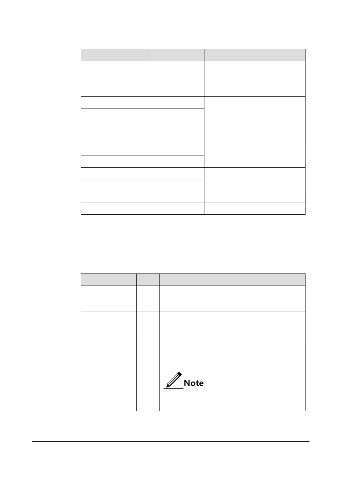
There are 26 LEDs on the OPCOM3500E-12MT panel, as listed in Table 19-4.
Table 19-4 LEDs on the OPCOM3500E-12MT panel
LED
Status
Description
PWR
Green
Power LED
Green: the power supply is normal.
Off: the power supply is abnormal.
SYS
Green
System status LED
Green: the CPU is working improperly.
Off: the CPU is working improperly.
Blinking green: the system is working properly.
TX
Green
Signaling output LED
Green: there is signaling being output.
Off: no signaling is being output.
The signaling direction is based on the magnetic
telephone. TX refers the direction from the
magnetic telephone to the 12MT.

Table of Contents

Questions and Answers:

Question and Answer IconNeed help?

Do you have a question about the Raisecom iTN2100 and is the answer not in the manual?

Raisecom iTN2100 Specifications

General IconGeneral
BrandRaisecom
ModeliTN2100
CategoryNetwork Hardware
LanguageEnglish

Related product manuals