EasyManuals Logo

Raisecom iTN2100 User Manual

Raisecom iTN2100
312 pages
To Next Page IconTo Next Page
To Previous Page IconTo Previous Page
Page #36 background imageLoading...
Page #36 background image
Raisecom
iTN2100 (P100R002) Hardware Description
Chassis
Raisecom Technology Co., Ltd.
7
No.
Name
Description
10
Chassis grounding terminal
Used to ground by the chassis
11
DC power interface
DC power input
2.2 Slots
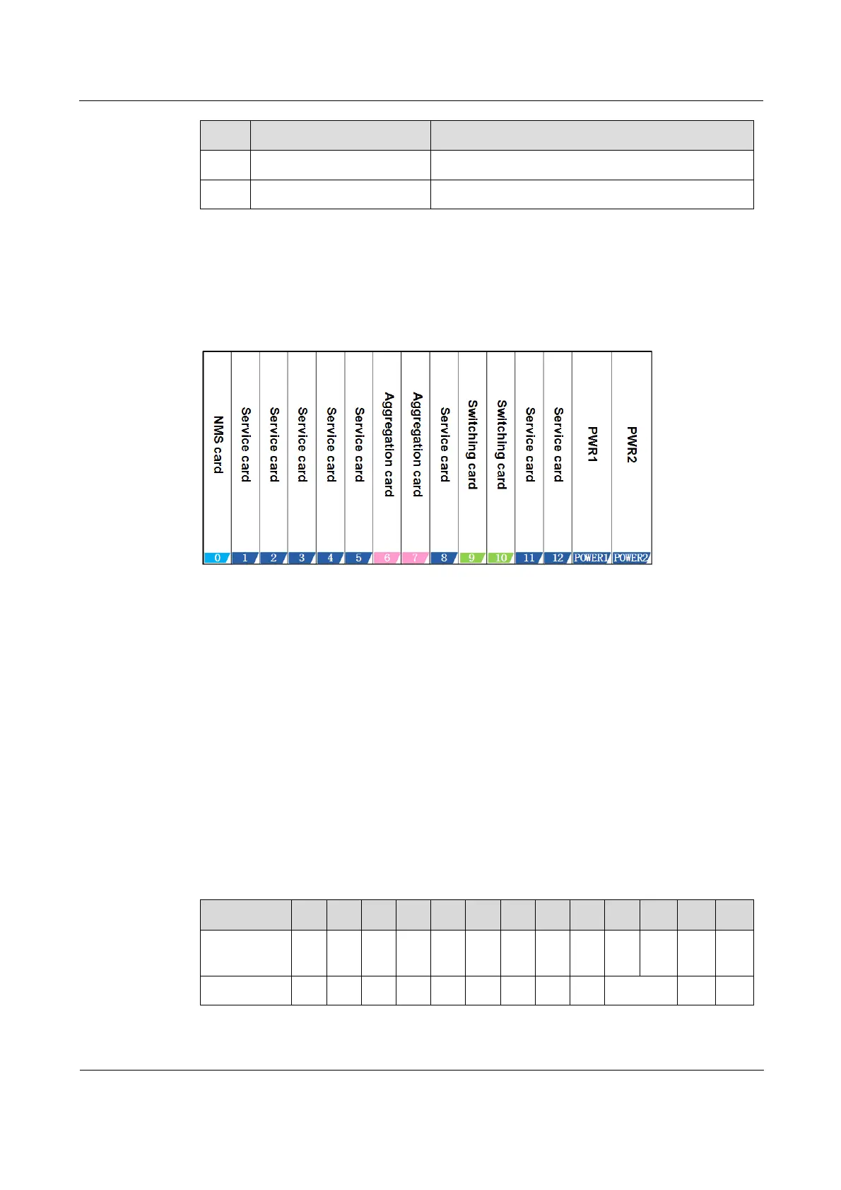
Figure 2-3 shows relations between slots and cards.
Figure 2-3 Relations between slots and cards
The corresponding relations are as below:
NMS card: plugged into slot 0 only.
Aggregation cards: plugged into slots 6 and 7 only.
Switching cards: plugged into slots 9 and 10 only.
Other service cards: plugged into slots 15 and 812.
Power supplies: plugged into slots POWER1 and POWER2 only.
2.3 VC4 and GE distribution
Table 2-2 lists VC4 and GE distribution.
Table 2-2 VC4 and GE distribution
Slot
0
1
2
3
4
5
6
7
8
9
10
11
12
VC4
capacity
1
4
1
4
1
1
1
1
1
1
GE capacity
2
2
2
2
2
0
0
2
2
2
2

Table of Contents

Questions and Answers:

Question and Answer IconNeed help?

Do you have a question about the Raisecom iTN2100 and is the answer not in the manual?

Raisecom iTN2100 Specifications

General IconGeneral
BrandRaisecom
ModeliTN2100
CategoryNetwork Hardware
LanguageEnglish

Related product manuals