Raisecom
iTN2100 (P100R002) Hardware Description
Raisecom Technology Co., Ltd.
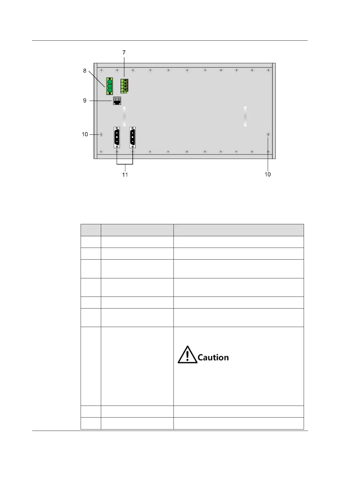
Figure 2-2 Rear panel of the chassis
Table 2-1 lists descriptions of the chassis.
Table 2-1 Descriptions of the chassis
Used to fix the chassis to a bench
Cards are plugged into slots 0–12.
Used to contain the dust-proof cotton to prevent
dust from accessing the device.
Power supply cards are plugged into slots POWER1
and POWRE2.
Used to fix the fan on the chassis
The fan is installed above the heat dissipating area
to dissipate hot air inside the chassis.
Four-hole spring terminal supporting one-way
alarm input and one-way alarm output
The DC voltage connected to the alarm
output terminal should not exceed 30 V and
the current should not exceed 1 A. The AC
voltage connected to the alarm output
terminal should not exceed 125 V and the
current should not exceed 0.3 A.
Fan power supply interface
Used to supply power to the fan
Used to connect to the fan and monitor its status