Raisecom
iTN2100 (P100R002) Hardware Description
Raisecom Technology Co., Ltd.
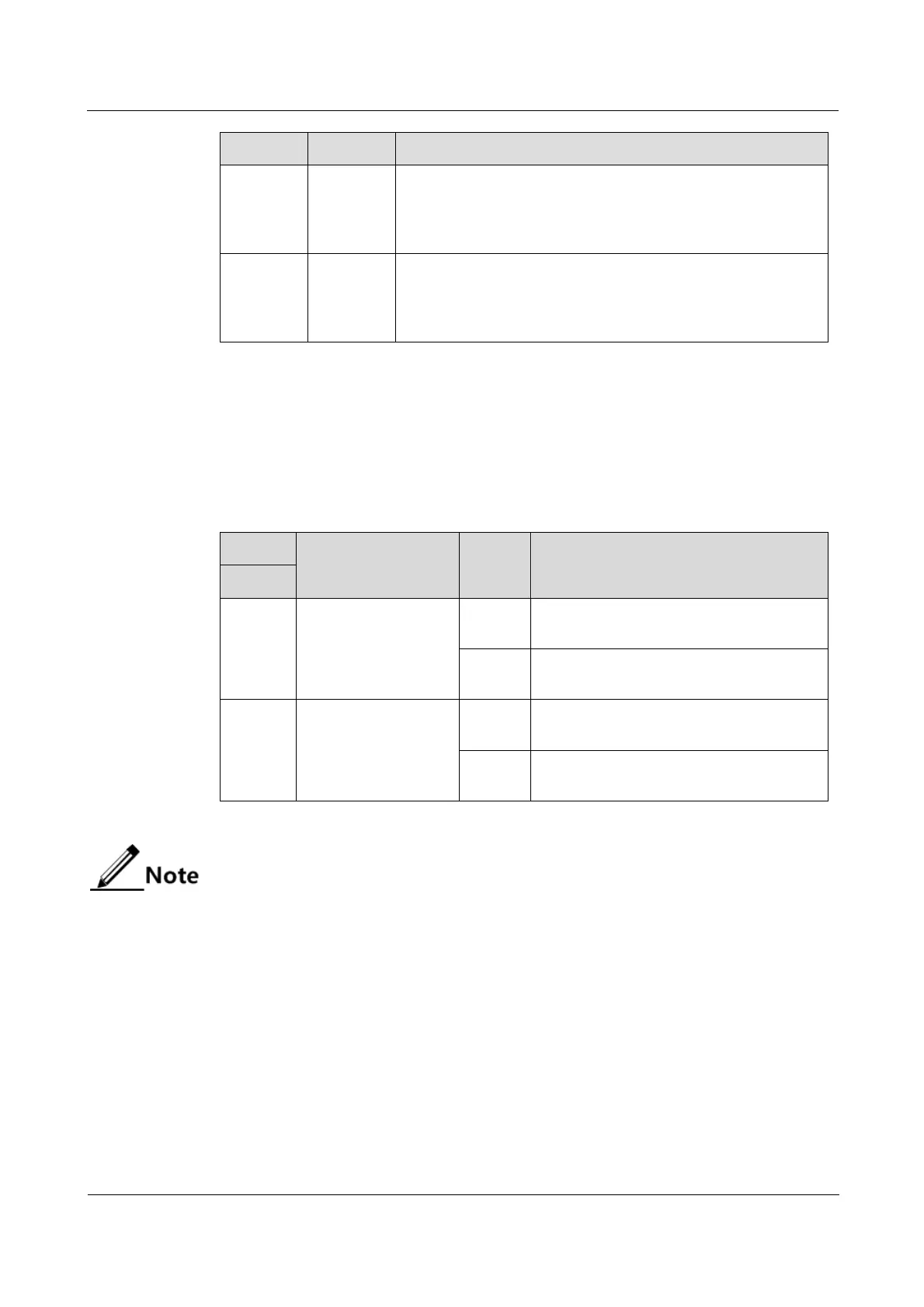
System status LED
Green: the system is working improperly.
Off: the system is working improperly.
Blinking green: the system is working properly.
Overall alarm LED
Red: TU-AIS or TU-LOP alarms are generated on configured
timeslots, or LOS alarms are generated on the E1 interface.
Off: no alarms are generated.
15.2.5 DIP switches
The OPCOM3500E-32E1 has no DIP switches.
The OPCOM3500E-32E1-BL has a DIP switch, as listed in Table 15-10.
Table 15-10 Configurations of the DIP switch SW1 on the OPCOM3500E-32E1-BL
Set the interface type
of E1 1–16.
Set the interface type of E1 1–16 to the
unbalanced interface.
Set the interface type of E1 1–16 to the
balanced interface.
Set the interface type
of E1 17–32.
Set the interface type of E1 17–32 to the
unbalanced interface.
Set the interface type of E1 17–32 to the
balanced interface.
By default, SW1 is all OFF. Namely, E1 1–32 are set to the balanced interface.
You can set the interface to balanced or unbalanced interface through software
or DIP switch.
15.2.6 Alarms
Table 15-11 lists alarms of the OPCOM3500E-32E1/32E1-BL.
 Loading...