Raisecom
iTN2100 (P100R002) Hardware Description
20 Service aggregation cards
Raisecom Technology Co., Ltd.
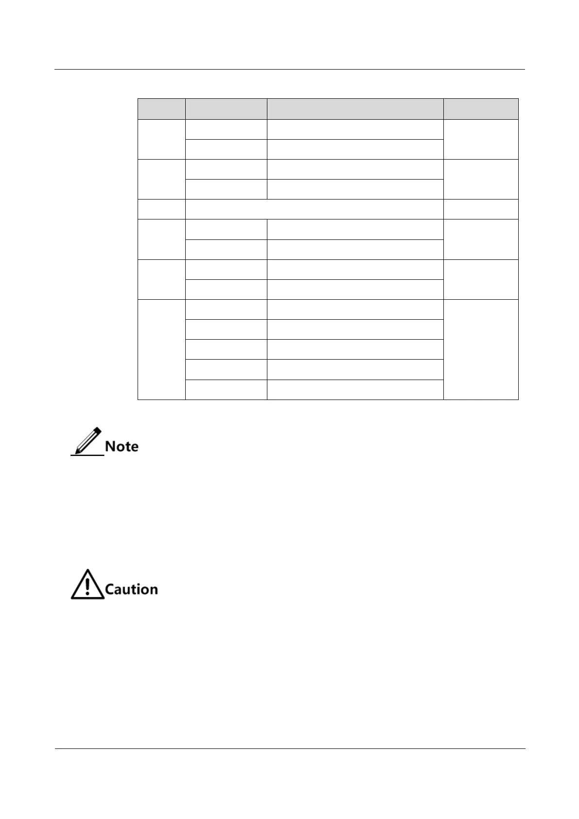
Table 20-6 BITs 1–8 of the DIP switch
Set to 2R mode and disable CDR.
Set to 3R mode and enable CDR.
Configure the speed manually.
Configure speed auto-negotiation.
Set the speed to 1000 Mbit/s Ethernet.
Set the speed to 100 Mbit/s Ethernet.
By default, BITs 1–8 of SW2, SW3, SW4, and SW5 are both set to OFF. It
means that failover and ALS are disabled and the card works in 2R mode (with
CDR being disabled).
Configurations on DIP switches are valid when they are powered on. After
configurations on DIP switches are changes, power them again to make new
configurations valid.
When BIT 4 is set to ON, BITs 5–8 are invalid.
When BITs 4 and 5 are set to OFF, BITs 6–8 are invalid.
When BIT 4 is set to OFF and BIT 5 is set to ON, BITs 6–8 are valid.
Before configuring DIP switching, you should confirm the attenuation value of the
fiber, ensuring the RX power of the line-side optical interfaces is in the specified
range. For details, see Table 20-2 Client-side interface metrics (optical modules),
Table 20-3 Client-side interface metrics (electrical modules), and Table 20-4 Line-side
interface metrics.
Configurations on DIP switches
Table 20-7 describes configurations on DIP switches of the iTN2100-Gb (A).