EasyManuals Logo

Raisecom iTN2100 User Manual

Raisecom iTN2100
312 pages
To Next Page IconTo Next Page
To Previous Page IconTo Previous Page
Page #43 background imageLoading...
Page #43 background image
Raisecom
iTN2100 (P100R002) Hardware Description
4 Power supplies
Raisecom Technology Co., Ltd.
14
4.1.3 LEDs
Table 4-1 lists LEDs on the SUB-PWRII-DC/DC-300 panel.
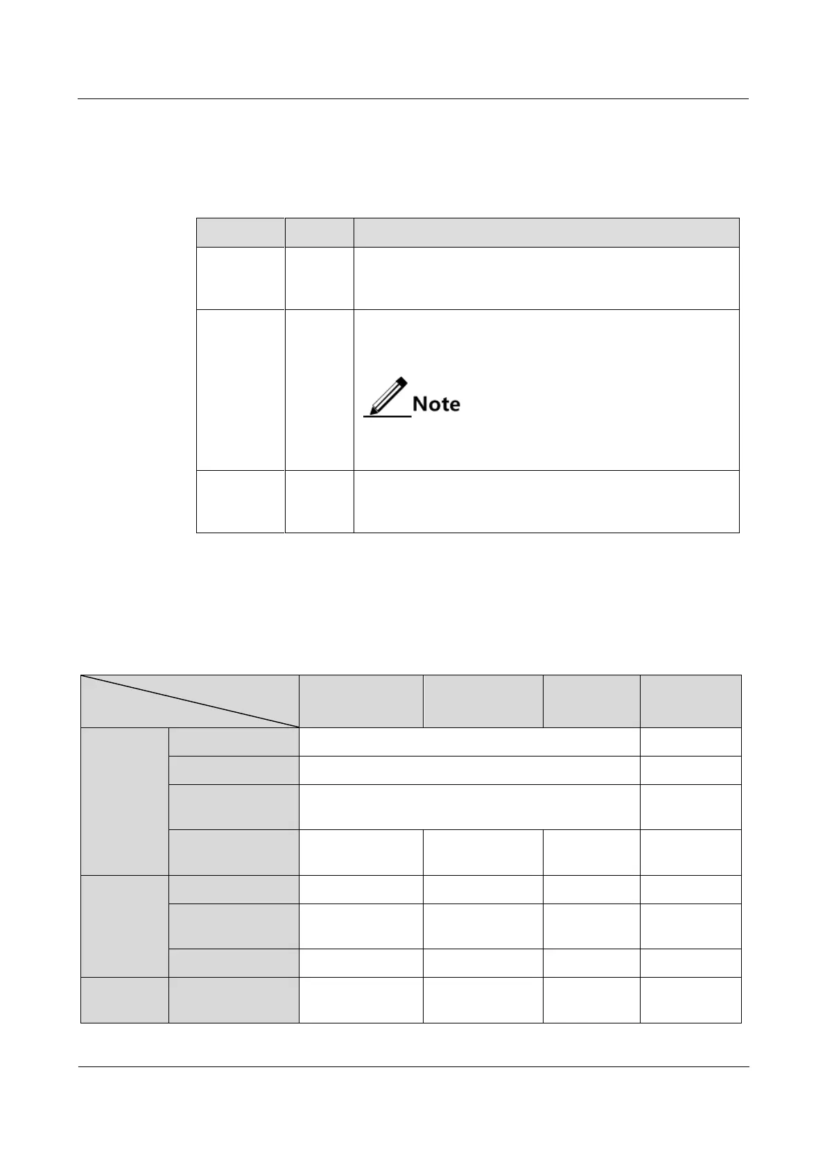
Table 4-1 LEDs on the SUB-PWRII-DC/DC-300 panel
LED
Status
Description
5V PWR
Green
+5 V power output LED
Green: +5 V power output is normal.
Off: +5 V power output is off.
5V ALM
Red
+5 V power alarm LED
Red: +5 V power output is off or the voltage is abnormal.
Off: +5 V voltage is normal.
Only when there is no voltage input for this power
supply and the other power supply is working properly,
the LED is probably red.
-48V
Green
-48 V power working LED
Green: -48 V power input is normal.
Off: -48 V power input is off.
4.1.4 Specifications
Table 4-2 lists specifications of the SUB-PWRII-DC/DC-300.
Table 4-2 Specifications of the SUB-PWRII-DC/DC-300
Card
Parameter
SUB-PWRII-DC
(-48 V/150 W)
SUB-PWRII-DC
(110 V/300 W)
SUB-PWRII-
DC-300
Remark
Basic
parameters
Dimensions
38.5 mm (width) × 224 mm (depth) × 240 mm (height)
Weight
1.05 kg
Zero-load power
comsuption
5 W
In rated input
voltage
Rated power
consumption
150 W
300 W
300 W
Input
parameters
Rated input voltage
-48 V
110 V
-48 V
Input voltage range
-36 V to -72 V
70140 V
-38.4 V to -
57.6 V
In full load
Rated input power
180 W
375 W
375 W
Protection
function
Input over pressure
protection
34 V
64 V
34 V

Table of Contents

Questions and Answers:

Question and Answer IconNeed help?

Do you have a question about the Raisecom iTN2100 and is the answer not in the manual?

Raisecom iTN2100 Specifications

General IconGeneral
BrandRaisecom
ModeliTN2100
CategoryNetwork Hardware
LanguageEnglish

Related product manuals