Raisecom
iTN2100 (P100R002) Hardware Description
Raisecom Technology Co., Ltd.
21.6 Grounding cables
21.6.1 Introduction
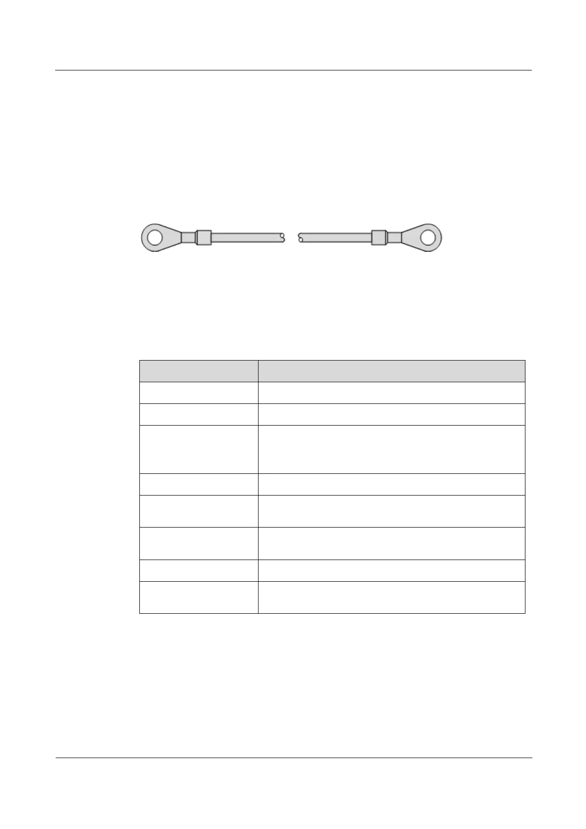
The grounding cable is used to ground the iTN2100 chassis.
21.6.2 Appearance
The grounding cable of the iTN2100 consists of OT terminals and co-axial cable, as listed in
Figure 21-12.
Figure 21-12 Grounding cable
21.6.3 Specifications
Table 21-9 lists specifications of the grounding cable of the iTN2100.
Table 21-9 Specifications of the grounding cable
Comply with the UL standard and meet RoHS requirements.
Yellow-green multi-strand copper-core conducting wire (1.25
mm
2
)
Electronic wire used UL1007 or UL1005
10 mm length and plated with tin
3.5/1.75 black heat-shrink tubing. It is a 20 mm plastic tube
which shrinks when heated.
The conducting and OT terminals adopts solderless crimped
connection.
Error in length of
conducting wire