EasyManuals Logo

Raisecom iTN2100 User Manual

Raisecom iTN2100
312 pages
To Next Page IconTo Next Page
To Previous Page IconTo Previous Page
Page #294 background imageLoading...
Page #294 background image
Raisecom
iTN2100 (P100R002) Hardware Description
21 Cables
Raisecom Technology Co., Ltd.
265
PIN
Defined output
Mark
Description
4
TXC_3
Clock egress interface 3
5
TXD_2
Data egress interface 2
6
TXC_2
Clock egress interface 2
7
TXD_1
Data egress interface 1
8
TXC_1
Clock egress interface 1
9, 10
NC
Idle
11
RXD_4
Data ingress interface 4
12
RXC_4
Clock ingress interface 4
13
RXD_3
Data ingress interface 3
14
RXC_3
Clock ingress interface 3
15
RXD_2
Data ingress interface 2
16
RXC_2
Clock ingress interface 2
17
RXD_1
Data ingress interface 1
18
RXC_1
Clock ingress interface 1
1926
GND
Grounding
21.12 V35-HDB26 cables
21.12.1 Introduction
The V35-HDB26 cable is used to connect the HDB26 female connector and other devices to
transmit V.35 services. The unshielded cable is used on V.35 interface card to ensure lightning
protection.
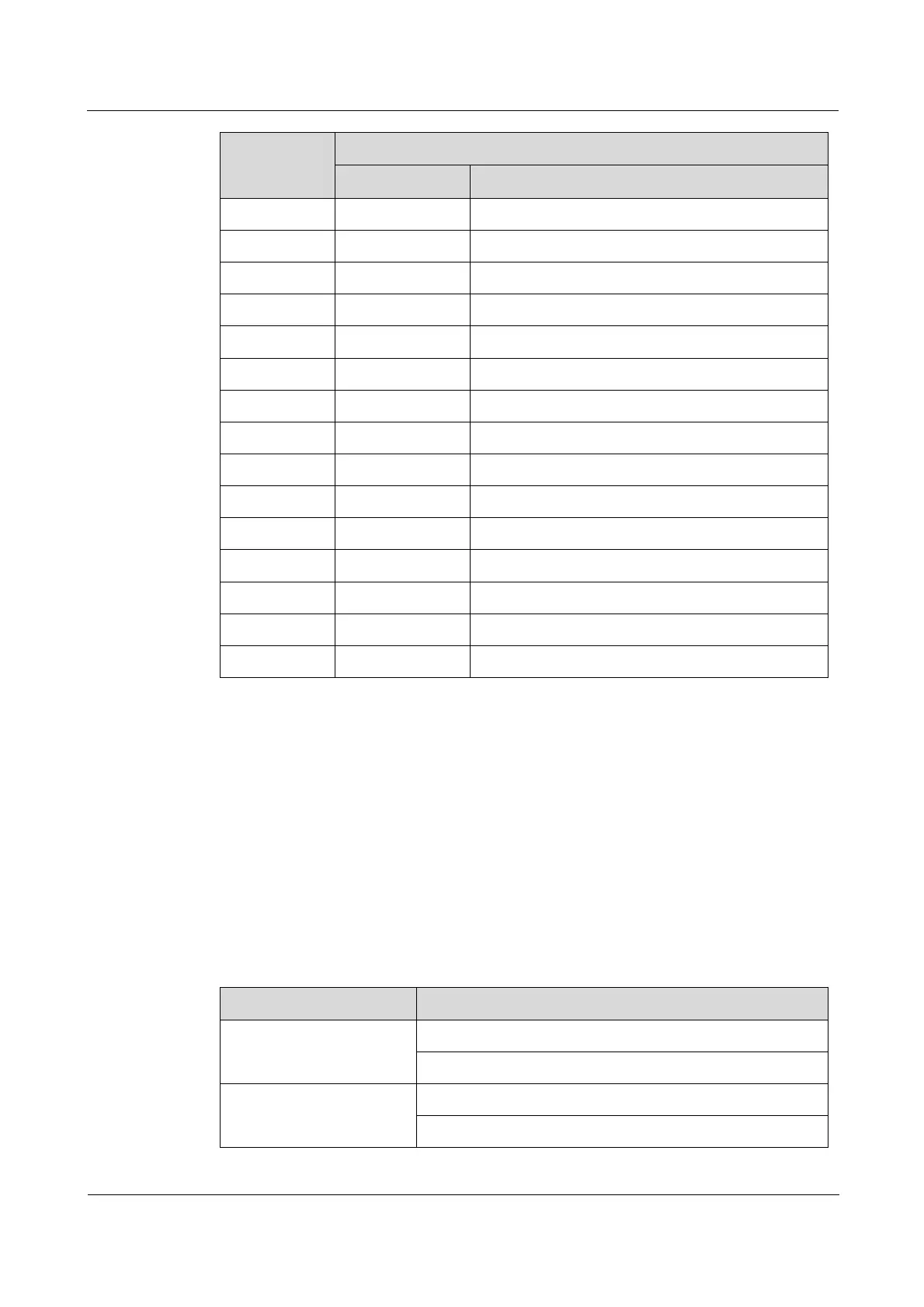
Table 21-26 lists relations between the V35-HDB26 cable and the card on the iTN2100.
Table 21-26 Relations between the V35-HDB26 cable and the card on the iTN2100
Card
Cable
OPCOM3500E-8V35
CBL-V35-HDB26M/2M34F (unshielded cable)
CBL-V35-HDB26M/2M34M (unshielded cable)
OPCOM3500E-435
CBL-V35-HDB26M/M34F (unshielded cable)
CBL-V35-HDB26M/M34M (unshielded cable)

Table of Contents

Questions and Answers:

Question and Answer IconNeed help?

Do you have a question about the Raisecom iTN2100 and is the answer not in the manual?

Raisecom iTN2100 Specifications

General IconGeneral
BrandRaisecom
ModeliTN2100
CategoryNetwork Hardware
LanguageEnglish

Related product manuals