EasyManuals Logo

Raisecom iTN2100 User Manual

Raisecom iTN2100
312 pages
To Next Page IconTo Next Page
To Previous Page IconTo Previous Page
Page #207 background imageLoading...
Page #207 background image
Raisecom
iTN2100 (P100R002) Hardware Description
15 PDH and RCMS cards
Raisecom Technology Co., Ltd.
178
Interface
Status
Description
LOS (AD)
LOS (14)
Red
Related nterface LOS alarm LED
Red: input LOS alarms are generated on the related
interface.
Off: no input LOS alarms are generated on the related
interface.
Blinking green: input LOS alarms are generated on the
remote device connected to the related interface.
15.10.5 DIP switches
Version A
The OPCOM3500E-120H×4 (version A) has two DIP switches: SW6 and SW7, as listed in
Table 15-54 and Table 15-54.
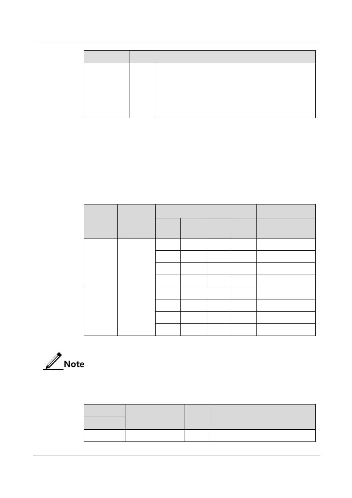
Table 15-54 Configurations of DIP switch SW6 on the OPCOM3500E-1204 (version A)
DIP
switch
Function
Status
Description
Bit1
Bit2
Bit3
Bit4
Optical interface
device
SW6
Set the type
of the
optical
interface
device.
ON
ON
ON
ON
M
ON
ON
ON
OFF
S1
ON
ON
OFF
ON
S2
ON
ON
OFF
OFF
S3
ON
OFF
ON
ON
SS13
ON
OFF
ON
OFF
SS15
ON
OFF
OFF
ON
SS23
ON
OFF
OFF
OFF
SS25
SW6 is properly configured before the card leaves the factory. Do not configure it if
not needed.
Table 15-55 Configurations of DIP switch SW7 on the OPCOM3500E-120H×4 (version A)
SW7
Function
Status
Description
DIP bit
Bit1
Enable or disable
ON
Enable ALS.

Table of Contents

Questions and Answers:

Question and Answer IconNeed help?

Do you have a question about the Raisecom iTN2100 and is the answer not in the manual?

Raisecom iTN2100 Specifications

General IconGeneral
BrandRaisecom
ModeliTN2100
CategoryNetwork Hardware
LanguageEnglish

Related product manuals