Raisecom
iTN2100 (P100R002) Hardware Description
Raisecom Technology Co., Ltd.
15.6.3 Interfaces
Interface types
There are five interfaces on the OPCOM3500E-120EOS×4L panel, as listed in Table 15-29.
Table 15-29 Interfaces on the OPCOM3500E-120EOS×4L
Service downlink interface
TX indicates sending and RX indicates receiving.
Interface parameters
Table 15-30 lists parameters of interfaces 1–4 on the OPCOM3500E-120EOS×4L.
Table 15-30 Parameters of interfaces 1–4 on the OPCOM3500E-120EOS×4L
SFP optical interface (LC)
15.6.4 LEDs
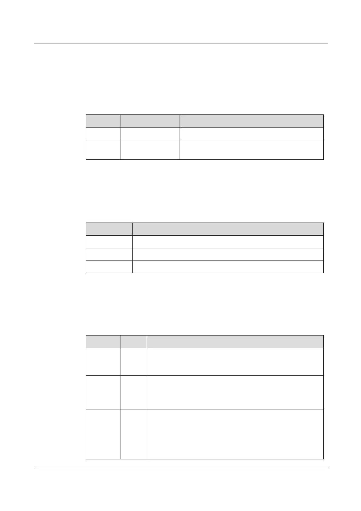
There are 10 LEDs on the OPCOM3500E-120EOS×4L panel, as listed in Table 15-31.
Table 15-31 LEDs on the OPCOM3500E-120EOS×4L panel
Power LED
Green: the power supply is normal.
Off: the power supply is abnormal.
System status LED
Green: the system is working improperly.
Off: the system is working improperly.
Blinking green: the system is working properly.
Interface 1/2/3/4 remote device LPR alarm LED
Red: after the local device and the remote device connected to
interface 1, 2, 3, or 4 are connected and work properly, LPR
occurs on the remote device.
Off: the remote device connected to interface 1, 2, 3, or 4 is
working properly.