EasyManuals Logo

Raisecom iTN2100 User Manual

Raisecom iTN2100
312 pages
To Next Page IconTo Next Page
To Previous Page IconTo Previous Page
Page #223 background imageLoading...
Page #223 background image
Raisecom
iTN2100 (P100R002) Hardware Description
16 V.24 card
Raisecom Technology Co., Ltd.
16-194
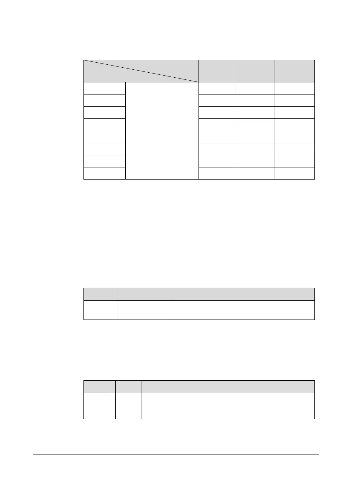
Table 16-1 Relations between V24 bandwidth and 64 Kbit/s timeslot on the OPCOM3500E-8V24
Bandwidth
V.24 data
64 Kbit/s
128 Kbit/s
256 Kbit/s
Line 1 V.24
Occupy the first E1.
TS1
TS12
TS14
Line 2 V.24
TS5
TS56
TS58
Line 3 V.24
TS17
TS1718
TS1720
Line 4 V.24
TS21
TS2122
TS2124
Line 5 V.24
Occupy the second E1.
TS1
TS12
TS14
Line 6 V.24
TS5
TS56
TS58
Line 7 V.24
TS17
TS1718
TS1720
Line 8 V.24
TS21
TS2122
TS2124
16.1.2 Slots
The OPCOM3500E-8V24 can be plugged into slots 15 and 812 on the iTN2100.
16.1.3 Interfaces
Interface types
There are two interfaces on the OPCOM3500E-8V24 panel, as listed in Table 16-2.
Table 16-2 Interfaces on the OPCOM3500E-8V24 panel
Interface
Connector type
Description
14, 58
HDB26 female
connector
Service downlink interface
Each interface can transmit four ways of V.24 data.
16.1.4 LEDs
There are 18 LEDs on the OPCOM3500E-8V24 panel, as listed in Table 16-3.
Table 16-3 LEDs on the OPCOM3500E-8V24 panel
Interface
Status
Description
PWR
Green
Power LED
Green: the power supply is normal.
Off: the power supply is abnormal.

Table of Contents

Questions and Answers:

Question and Answer IconNeed help?

Do you have a question about the Raisecom iTN2100 and is the answer not in the manual?

Raisecom iTN2100 Specifications

General IconGeneral
BrandRaisecom
ModeliTN2100
CategoryNetwork Hardware
LanguageEnglish

Related product manuals