Raisecom
iTN2100 (P100R002) Hardware Description
Raisecom Technology Co., Ltd.
System status LED
Green: the system is down or fails.
Off: the CPU is working improperly.
Blinking green: the system is working properly.
If the 4 LEDs are in green, it indicates that the MULTI-
FXS, MULTI-FXO, MULTI-V24, and MULTI-RS485
are inserted into the iTN2100.
Indicate the usage status of the voice channel. The LED
is lighten up for local off-hook (outputting signaling),
local ringing (inputting signaling), and conversation. It
indicates that the voice channel is being used.
Indicate the usage status of the data channel. The LED is
in blinking green when the data is being received or sent.
The blinking frequency is related to the data frequency.
19.2.5 DIP Switch
Table 19-18 lists the DIP switch on the OPCOM3500E-MULTI. After the DIP switch is
configured by the software, default configurations of the DIP switch are invalid.
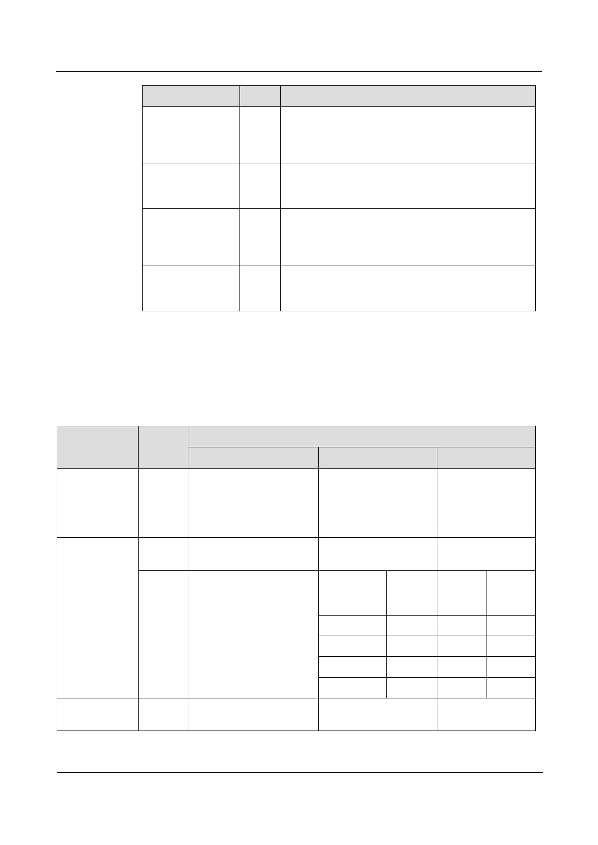
Table 19-18 DIP switch on the OPCOM3500E-MULTI
Voice interface
configuration
Configure polarity
inversion of FXS interfaces.
Note that polarity inversion
configured through the
software is invalid.
2/4W interface
configuration
Configure 2/4W interface
modes.
Set the default gain value
(providing 4 commonly-
used values).
Gain value
configuration
(A-D/D-A)
Data interface
configuration
Configure V.24 interface
modes.