EasyManuals Logo
Home>Raisecom>Network Hardware>iTN2100

Raisecom iTN2100 User Manual

Raisecom iTN2100
312 pages
To Next Page IconTo Next Page
To Previous Page IconTo Previous Page
Page #154 background imageLoading...
Page #154 background image
Raisecom
iTN2100 (P100R002) Hardware Description
14 EOS cards
Raisecom Technology Co., Ltd.
125
Interface
Status
Description
SD
(14)
Green
Optical signal detection LED
Green: optical signals are detected.
Off: no optical signals are detected.
LNK/ACT
(14)
Green
Line working LED
Green: the interface is working properly.
Off: the interface is disconnected or is working improperly.
Blinking green: the interface is receiving or sending data.
14.3.5 DIP switches
Table 14-13 and Table 14-14 list configurations of DIP switches on the OPCOM3500E-
4EOS-4FX.
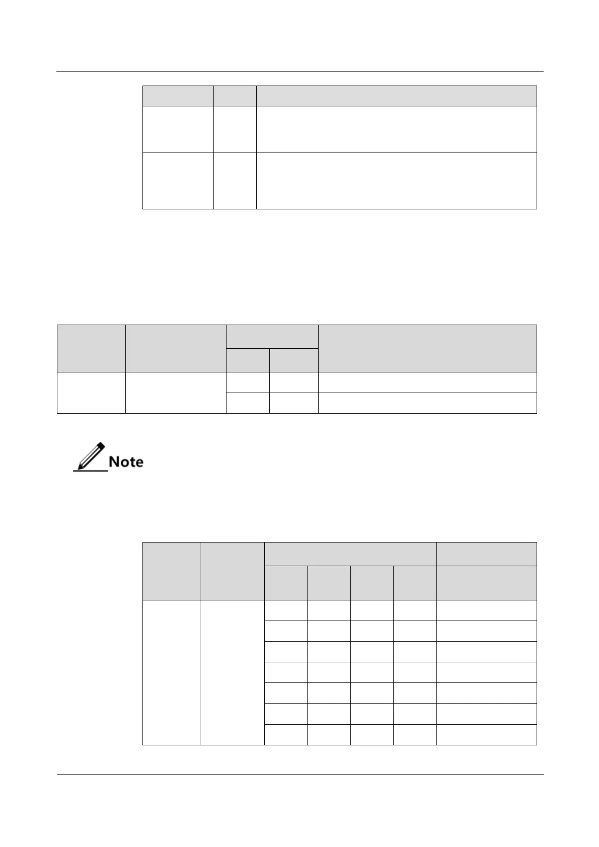
Table 14-13 Configurations of DIP switch SW1 on the OPCOM3500E-4EOS-4FX
DIP switch
Function
Status
Description
Bit1
Bit2
SW1
Set working mode of
the card
ON
ON
Set the card in ESW working mode.
OFF
OFF
Set the card in EOS working mode.
By default, SW1 is all OFF. Namely, the card is working in EOS mode by default.
After you set working mode of SW1, configurations take effect after power-on.
Configuring SW1 during power-on is not supported.
Table 14-14 Configurations of DIP switch SW2 on the OPCOM3500E-4EOS-4FX
DIP
switch
Function
Status
Description
Bit1
Bit2
Bit3
Bit4
Optical interface
device
SW2
Set the type
of optical
interface
device.
ON
ON
ON
ON
M
ON
ON
ON
OFF
S1
ON
ON
OFF
ON
S2
ON
ON
OFF
OFF
S3
ON
OFF
ON
ON
SS13
ON
OFF
ON
OFF
SS15
ON
OFF
OFF
ON
SS23

Table of Contents

Questions and Answers:

Question and Answer IconNeed help?

Do you have a question about the Raisecom iTN2100 and is the answer not in the manual?

Raisecom iTN2100 Specifications

General IconGeneral
BrandRaisecom
ModeliTN2100
CategoryNetwork Hardware
LanguageEnglish

Related product manuals