Raisecom
iTN2100 (P100R002) Hardware Description
Raisecom Technology Co., Ltd.
SW2 is properly configured before the card leaves the factory. Do not configure it if
not needed.
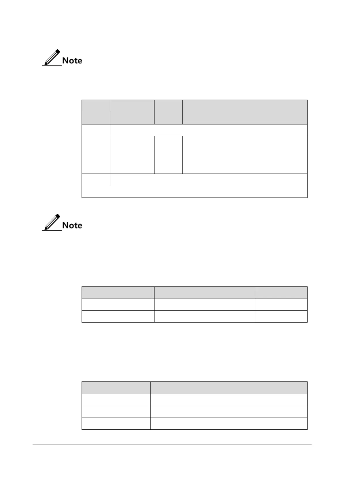
Table 14-21 Configurations of DIP switch SW3 on the OPCOM3500E-8EOS-FE
Set the egress
interface of
Ethernet
services.
Set the backplane interface to the egress
interface of Ethernet services.
Set the front plane interface to the egress
interface of Ethernet services.
By default, Bit2 of SW3 is OFF.
14.4.6 Alarms
Table 14-22 lists alarms of the OPCOM3500E-8EOS-FE.
Table 14-22 Alarms of the OPCOM3500E-8EOS-FE
Ethernet link failure alarm
The Ethernet cable is disconnected.
14.4.7 Specifications
Table 14-23 lists specifications of the OPCOM3500E-8EOS-FE.
Table 14-23 Specifications of the OPCOM3500E-8EOS-FE
25 mm (width) × 232 mm (depth) × 240 mm (height)