EasyManua.ls Logo

Raisecom iTN2100 - Cbl-E1-Db37 F;16 Bncf; Figure 21-16 CBL-E1-DB37 F;16 BNCF Cable; Table 21-15 Specifications of the CBL-E1-DB37 F;16 BNCF Cable

Raisecom iTN2100
312 pages
Print Icon
To Next Page IconTo Next Page
To Previous Page IconTo Previous Page
Loading...
Raisecom
iTN2100 (P100R002) Hardware Description
21 Cables
Raisecom Technology Co., Ltd.
257
PIN
Definition
Mark
PIN
Definition
Mark
11
OUT5-
TX5
30
IN5-
12
OUT5+
31
IN6+
RX6
13
OUT6-
TX6
32
IN6-
14
OUT6+
33
IN7+
RX7
15
OUT7-
TX7
34
IN7-
16
OUT7+
35
IN8+
RX8
17
OUT8-
TX8
36
IN8-
18
OUT8+
37
19
The PIN marked "+" is connected to the core of the co-axial cable.
The PIN marked "-" is connected to the shielding layer of the co-axial cable.
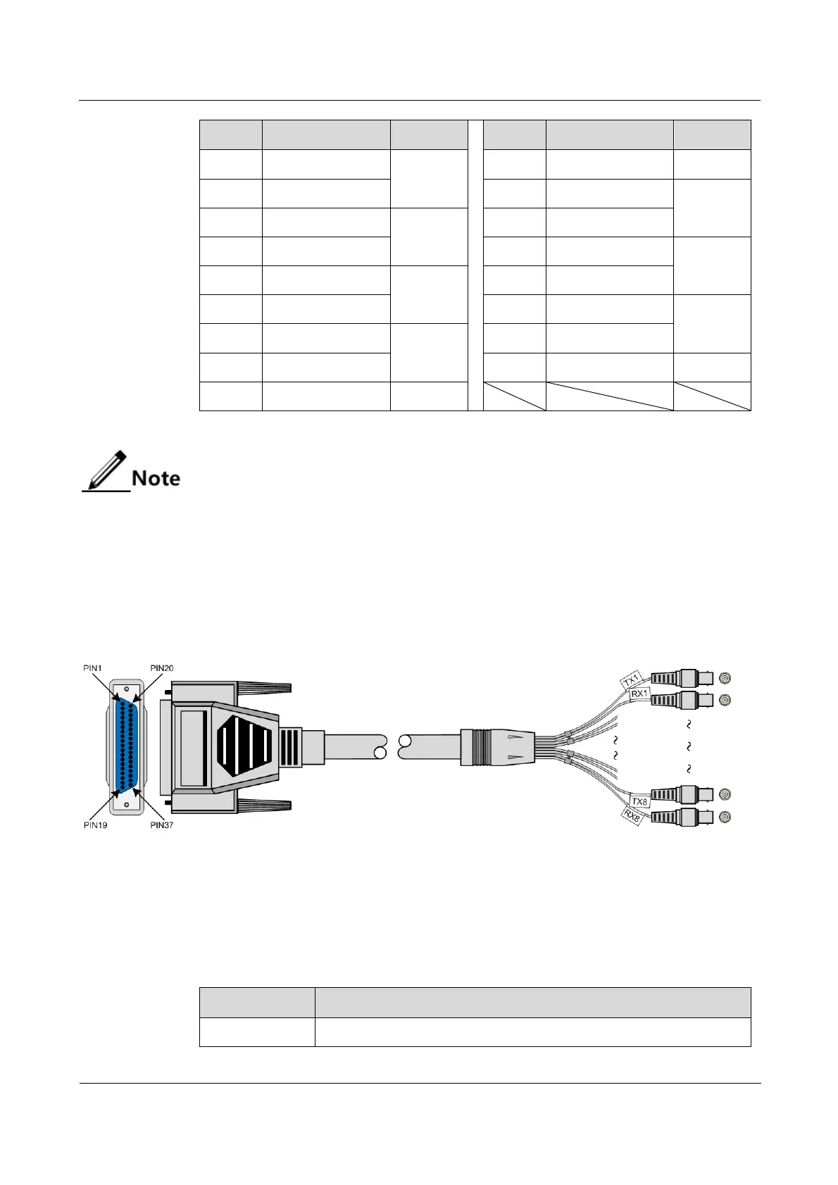
21.9.3 CBL-E1-DB37F/16BNCF
Appearance
Figure 21-16 shows the CBL-E1-DB37F/16BNCF cable.
Figure 21-16 CBL-E1-DB37F/16BNCF cable
Specifications
Table 21-15 lists specifications of the CBL-E1-DB37F/16BNCF cable.
Table 21-15 Specifications of the CBL-E1-DB37F/16BNCF cable
Parameter
Description
Name
CBL-E1-DB37F/16BNCF

Table of Contents

Related product manuals