Raisecom
iTN2100 (P100R002) Hardware Description
Raisecom Technology Co., Ltd.
Comply with ITU-T G.703 recommendations.
Comply with ITU-T G.823 recommendations.
Comply with ITU-T G.823 recommendations.
15.12.4 LEDs
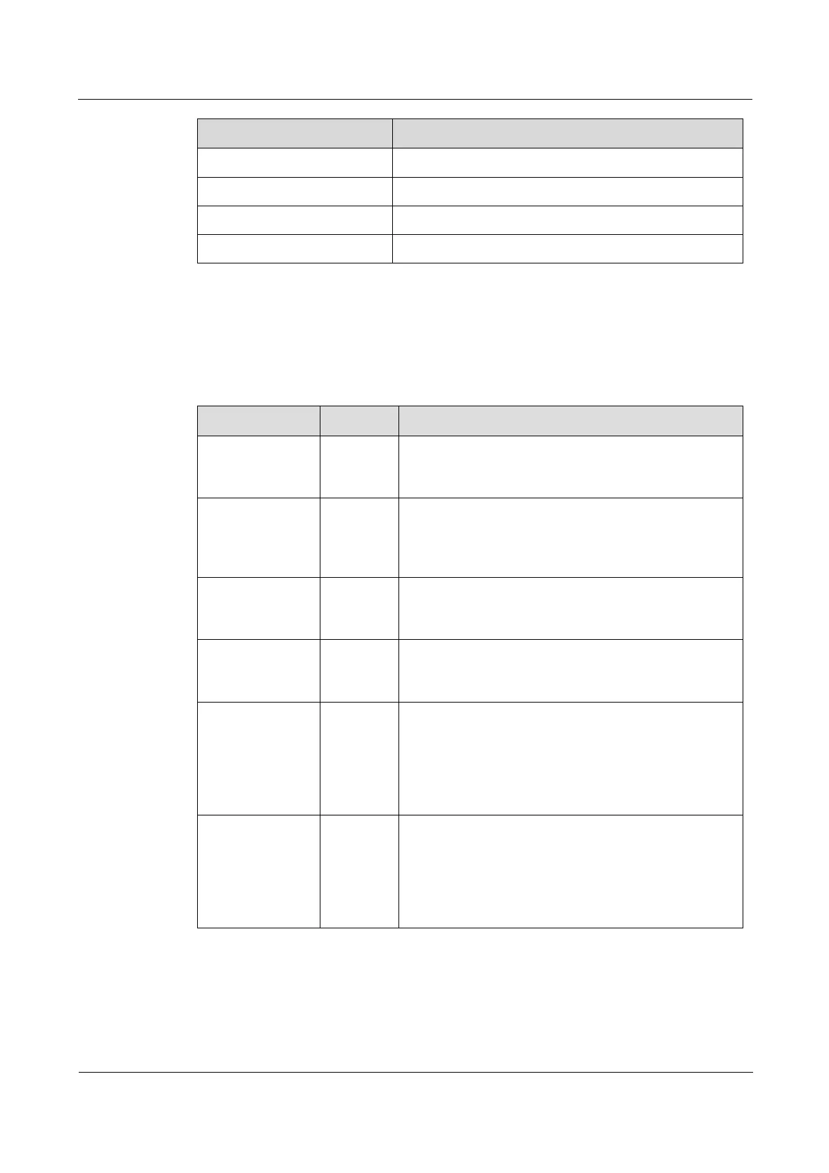
There are 10 LEDs on the OPCOM3500E-3DS3/E3 panel, as listed in Table 15-70.
Table 15-70 LEDs on the OPCOM3500E-3DS3/E3 panel
Power LED
Green: the power supply is normal.
Off: the power supply is abnormal.
System status LED
Green: the system is working improperly.
Off: the system is working improperly.
Blinking green: the system is working properly.
DS3/E3 LED
Green: the card is working in DS3 mode.
Off: the card is working in E3 mode.
Overall alarm LED
Green: alarms are generated on the card.
Off: no alarms are generated on the card.
Optical interface 1/2/3 status LED
Green: optical interface 1, 2, or 3 is enabled and
working properly.
Red: optical interface 1, 2, or 3 is enabled and LOS
alarms are generated on it.
Off: optical interface 1, 2, or 3 is disabled.
Electrical interface 1/2/3 status LED
Green: electrical interface 1, 2, or 3 is enabled and
working properly.
Red: electrical interface 1, 2, or 3 is enabled and LOS
alarms are generated on it.
Off: electrical interface 1, 2, or 3 is disabled.
15.12.5 DIP switches
The OPCOM3500E-3DS3/E3 has two DIP switches: SW1 and SW2, as listed in Table 15-71
and Table 15-72.