Raisecom
iTN2100 (P100R002) Hardware Description
Raisecom Technology Co., Ltd.
5.1.4 Buttons
There are two buttons on the iTN2100-NMS panel, as listed in Table 5-4.
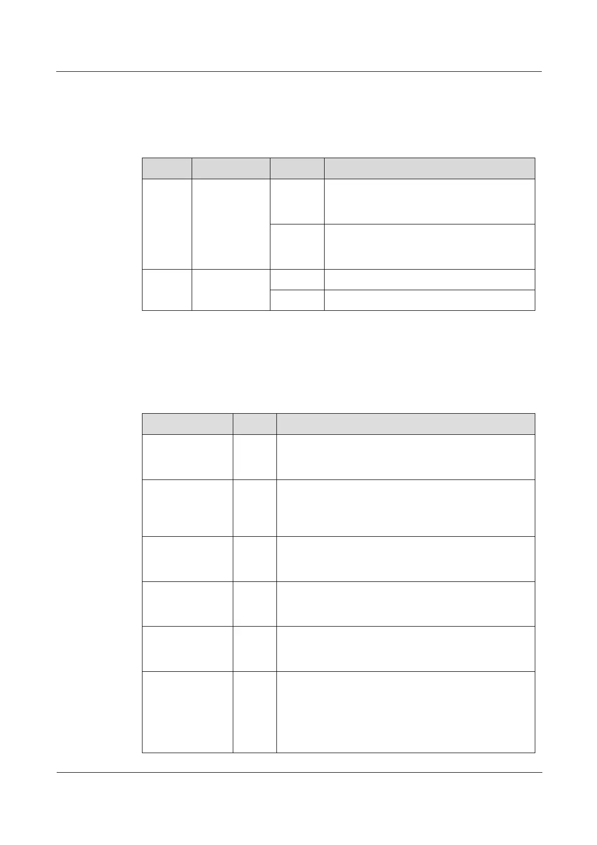
Table 5-4 Buttons on the iTN2100-NMS panel
In this status, when an alarm is being
generated, the buzzer is mute. You cannot
change this status through software.
In this status, when an alarm is being
generated, the buzzer rings. You can shield
this status through software.
The card is working properly.
You can press this button to reset the card.
5.1.5 LEDs
There are eight LEDs on the iTN2100-NMS panel, as listed in Table 5-5.
Table 5-5 LEDs on the iTN2100-NMS panel
Power LED
Green: the power supply is normal.
Off: the power supply is abnormal.
System status LED
Green: the system is working improperly.
Off: the system is working improperly.
Blinking green: the system is working properly.
Primary/Slave mode LED of the system clock
Green: the system clock is primary.
Off: the system clock is slave.
Alarm LED
Red: the communication fails or the clock fails.
Off: there is no alarm on communication or clock.
SNMP interface rate LED
Green: the Ethernet rate is 100 Mbit/s.
Off: the Ethernet rate is 10 Mbit/s.
SNMP interface working LED
Green: the SNMP interface is working properly.
Off: the SNMP interface is disconnected or is working
improperly.
Blinking green: the SNMP interface is receiving or
sending data.