X35 Monitor Air Seeder Setup
6.69
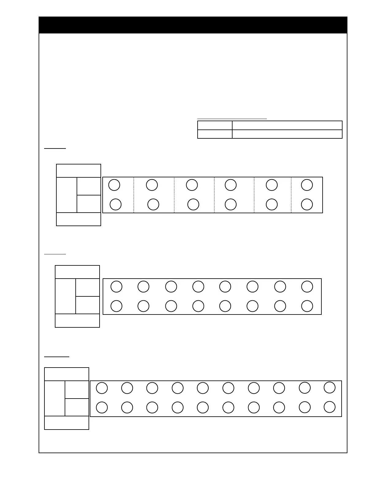
c. Assign each sensor to the appropriate Head
to show up correctly represented on the
monitor.
d. For units with sectional control, there will
be a 3rd column labelled Section.
i. Assign the sensor to the appropriate
boom and section so it is disabled
when that section is switched off.
1/41 2/42 3/43 4/44 5/45 6/46
12/52 11/51 10/50
9/49 8/48 7/47
HEAD 7
FERT1
HEAD 3
SEED3
HEAD 2
SEED2
HEAD 1
SEED1
HEAD 4
SEED4
HEAD 5
SEED5
HEAD 6
SEED6
6 PORT
FRONT OF DRILL
Figure 6.88 - Sensor Wiring
8 PORT
FRONT OF DRILL
10 PORT
FRONT OF DRILL
SECTION 1 SECTION 2 SECTION 3 SECTION 4 SECTION 5 SECTION 6
HEAD 8
FERT2
HEAD 9
FERT3
HEAD 10
FERT4
HEAD 11
FERT5
HEAD 12
FERT6
Legend - Naming Convention:
Red Implement was created using Custom profile
Blue Implement was
created using Factory profile
SECTION 1 SECTION 2 SECTION 3 SECTION 4 SECTION 5 SECTION 6 SECTION 7 SECTION 8
1/41 2/42 3/43 4/44 5/45 6/46
16/56 15/55 14/54 13/53 12/52 11/51
HEAD 3
SEED3
HEAD 2
SEED2
HEAD 1
SEED1
HEAD 4
SEED4
HEAD 5
SEED5
HEAD 6
SEED6
HEAD 9
FERT1
HEAD 10
FERT2
HEAD 1
1
FERT3
HEAD 12
FERT4
HEAD 7
SEED7
HEAD 8
SEED8
HEAD 13
FERT5
HEAD 14
FERT6
HEAD 15
FERT7
HEAD 16
FERT8
7
/47
10/50
8/48
9/49
Fertilizer Heads
Sensors
Fertilizer
Seed
Seed Heads
SECTION 1
SECTION 2 SECTION 3 SECTION 4 SECTION 5 SECTION 6 SECTION 7 SECTION 8
1/41 2/42 3/43 4/44 5/45 6/46
20/60 19/59 18/58 17/57 16/56 15/55
HEAD 3
SEED3
HEAD 2
SEED2
HEAD 1
SEED1
HEAD 4
SEED4
HEAD 5
SEED5
HEAD 6
SEED6
HEAD 11
FERT1
HEAD 12
FERT2
HEAD 13
FERT3
HEAD 14
FERT4
HEAD 7
SEED7
HEAD 8
SEED8
HEAD 15
FERT5
HEAD 16
FERT6
HEAD 17
FERT7
HEAD 18
FERT8
7/47
14/54
8/48
13/53
SECTION 8
HEAD 9
SEED9
HEAD 19
FERT9
9
/49
12/52
SECTION 8
HEAD 10
SEED10
HEAD 20
FERT10
10/50
11/51
Fertilizer Heads
Sensors
Fertilizer
Seed
Seed Heads
Fertilizer Heads
Sensors
Fertilizer
Seed
Seed Heads
e. When setting up corresponding heads and
sections, refer to Figure 6.88.
i. This shows how the blockage
sensors are
wired from the factory
and should be assigned to show up
correctly on the screen.