X35 ConsoleField / Job
9.10
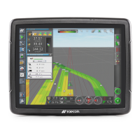
Figure 9.15 - Headland Option Menu
A
B
C
D
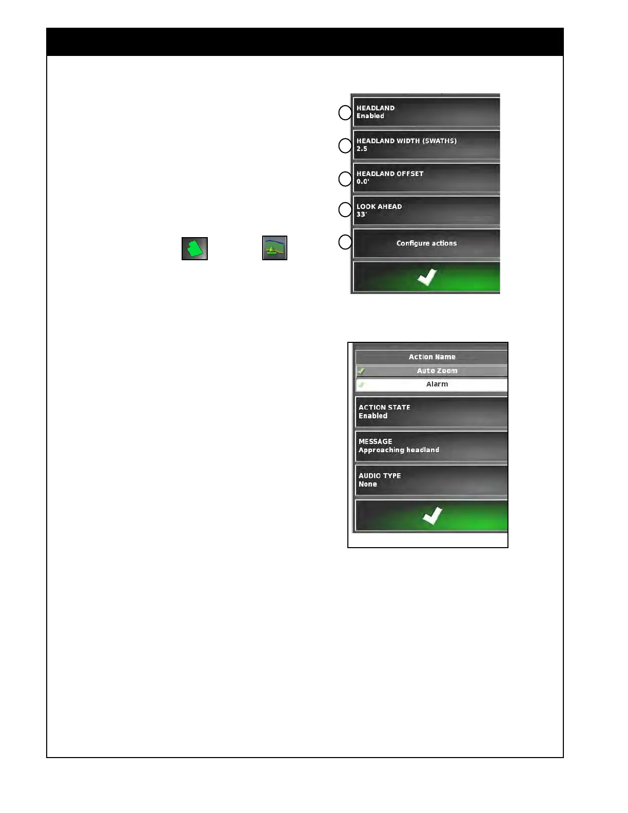
Figure 9.16 - Setting Headland Action - Alarm
9.2.6 Headland Options
Important
Headland boundaries show up as an orange line
on the guidance screen. A headland boundary
will only be created if a field boundary has first
been established.
To set up the working headland follow the steps
below.
1. Select the Field Menu
and select
Headland.
2. The Headland Option window will appear,
refer to Figure 9.15.
3.
Select the Headland button and set to enabled
to use this feature (Item A, Figure 9.15).
4.
Set the Headland Width;
a. Select the Headland Width (Item B, Figure
9.15).
b.
Enter the desired width, measured in
swaths from the inside of the field
boundary.
i. A swath, is the working width of the
implement.
ii.
Confirm your selections.
5. Set the Headland Offset (if required);
a. A positive headland offset will increase the
width of the headland.
b. A negative headland offset will decrease
the width of the headland.
i. Select a Headland Offset (Item C,
Figure 9.15).
ii.
Enter the offset distance and confirm.
E
6. Set the Look Ahead distance;
a. The Look Ahead Distance is a distance in
front of the vehicle, that the system will
look to respond with actions.
i. For example, when approaching the
headland an alarm will sound and/or
a warning message will be displayed
(depending on the alarm settings).
ii. Select Look Ahead, (Item D, Figure
9.15).
iii. Enter the distance and confirm.